This article discusses an automatic street lighting system based on Siemens TIA-Portal. The system can control the on/off status of the lights based on light intensity levels (lumens) or the presence of vehicles and pedestrians. The goal is to enhance energy efficiency and improve road safety. This system utilizes a comparator function to control the lighting by comparing the actual light intensity (PV) with the minimum light intensity threshold (SV).
Program Objective
Mode Selection:
Set the selector switch to the “Normal” or “Power Saving” position to select the desired mode.
Normal Mode:
Light Measurement: The light sensor measures the surrounding brightness level in real-time.
Lumen Level: The light level is measured in lumens.
Light Adjustment:
- If the lumen is less than 30: All 4 lights turn On.
- If the lumen is between 31-60: 2 lights turn On.
- If the lumen is between 61-120: 1 light turns On.
Power Saving Mode:
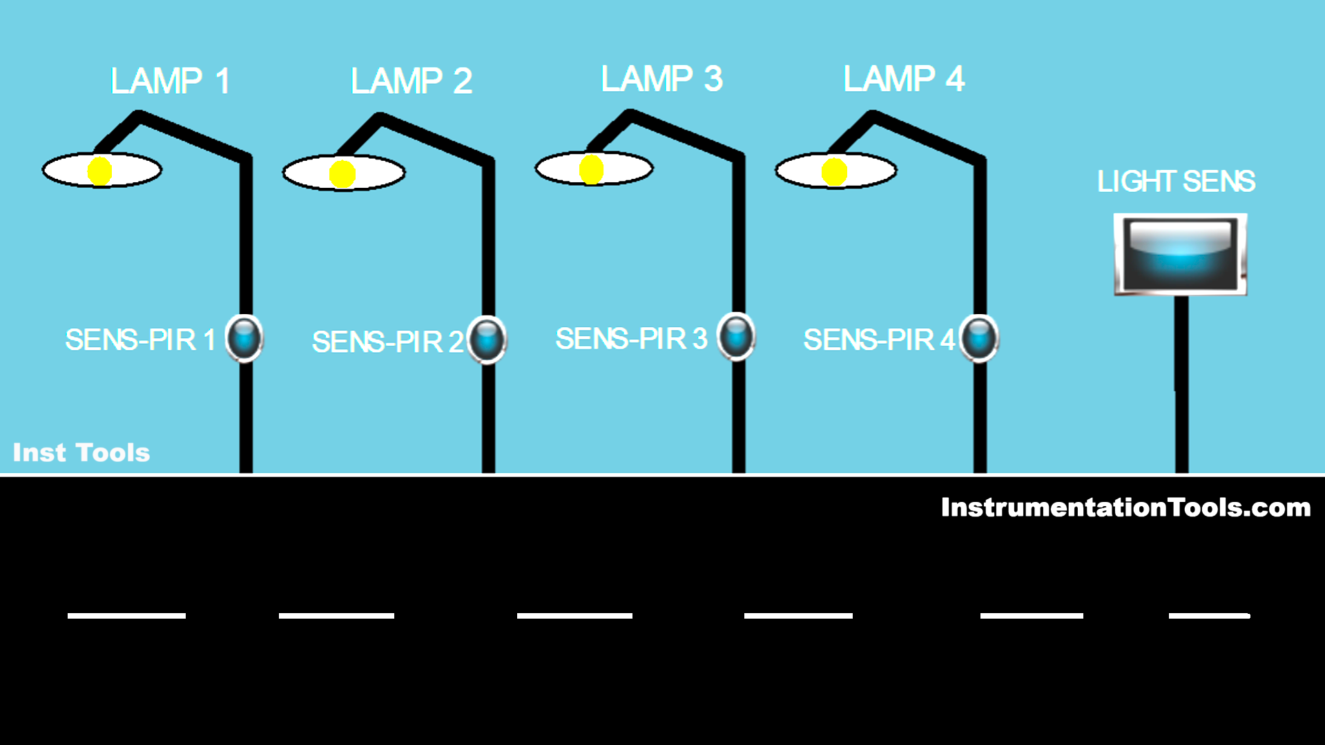
- Sensor Activation: The lights are activated by a PIR sensor that detects vehicle or pedestrian movement.
- Individual Sensors: Each light (total of 4 lights) has its own motion/PIR sensor.
- On-Demand Lighting: The lights only turn on when the sensor detects movement.
Mapping Details
| S.No. | Comment | Input (I) | Output(Q) | Memory Word | Memory Bit | Timer |
| 1 | PB_START | I0.0 | ||||
| 2 | PB_STOP | I0.1 | ||||
| 3 | NORMAL_OR_SAVING | I0.2 | ||||
| 4 | PIR_SENS1 | I0.3 | ||||
| 5 | PIR_SENS2 | I0.4 | ||||
| 6 | PIR_SENS3 | I0.5 | ||||
| 7 | PIR_SENS4 | I0.6 | ||||
| 8 | LAMP1 | Q0.0 | ||||
| 9 | LAMP2 | Q0.1 | ||||
| 10 | LAMP3 | Q0.2 | ||||
| 11 | LAMP4 | Q0.3 | ||||
| 12 | LUMENS_PV | MW2 | ||||
| 13 | SYSTEM_ON | M0.0 | ||||
| 14 | IR1_PIR1 | M0.1 | ||||
| 15 | IR1_PIR2 | M0.2 | ||||
| 16 | IR1_PIR3 | M0.3 | ||||
| 17 | IR1_PIR4 | M0.4 | ||||
| 18 | IR_SAVING_1 | M0.5 | ||||
| 19 | IR_SAVING_2 | M0.6 | ||||
| 20 | IR_SAVING_3 | M0.7 | ||||
| 21 | IR_TIMER1 | M1.0 |
Street Light Control Based on Light Intensity
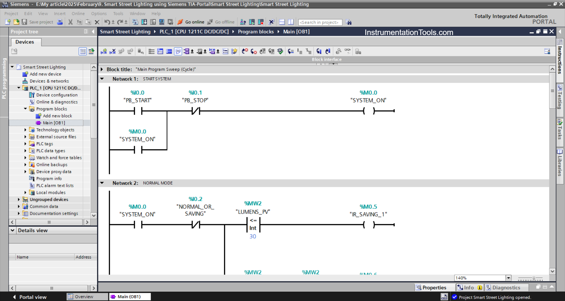
NETWORK 1 (START SYSTEM)
In this network, the memory bit SYSTEM_ON (M0.0) will be in the HIGH state when the PB_START (I0.0) button is Pressed. Even though the PB_START (I0.0) button has been Released, the memory bit SYSTEM_ON (M0.0) will remain in the HIGH state. Because it uses Latching.
The memory bit SYSTEM_ON (M0.0) will be in the LOW state if the PB_STOP (I0.1) button is Pressed.
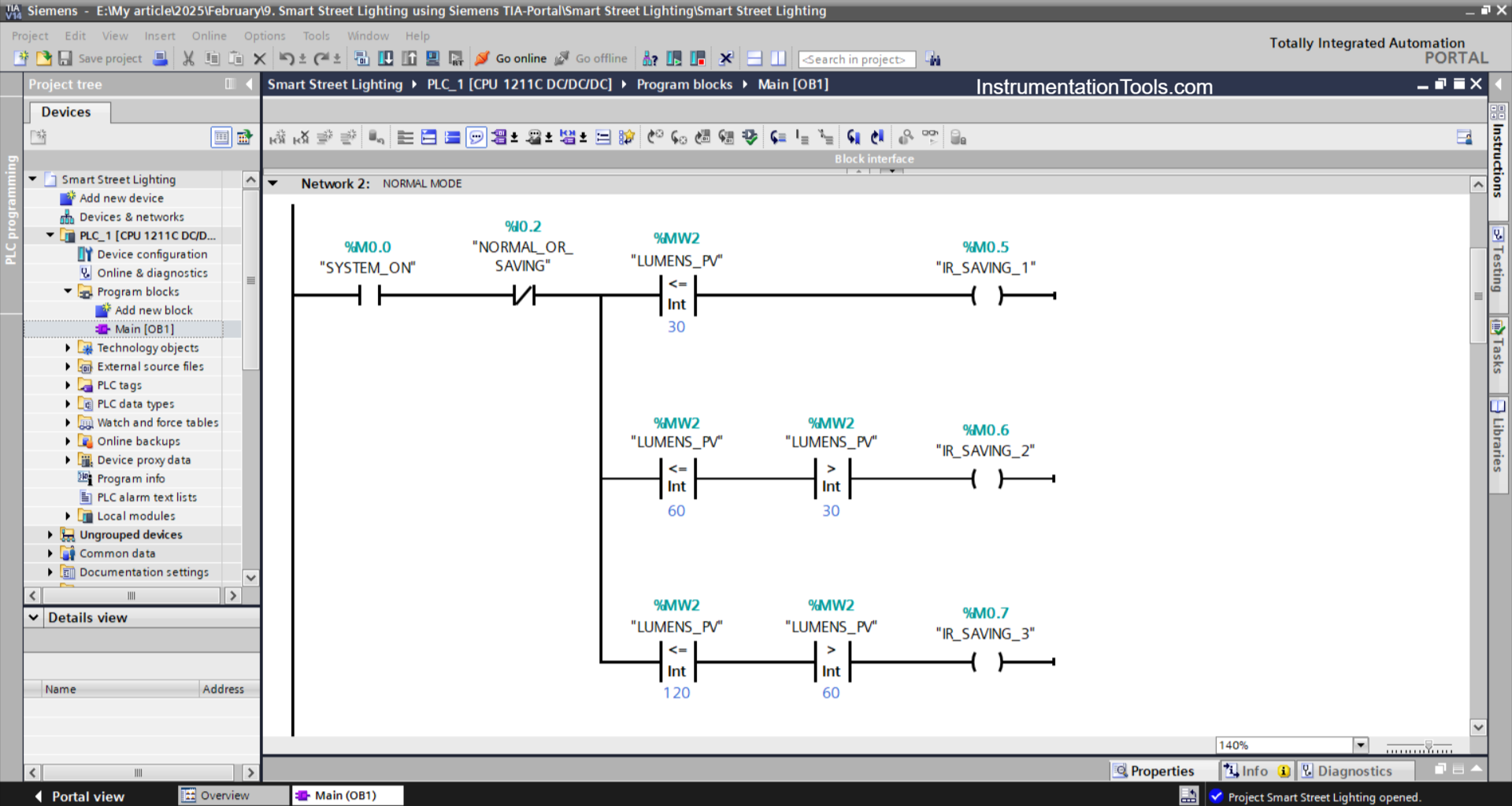
NETWORK 2 (NORMAL MODE)
In this network, when the NO contact of the memory bit SYSTEM_ON(M0.0) is in the HIGH state and the value in the word memory LUMENS_PV (MW2) is Less Than or Equal to “30”, then the memory bit IR_SAVING_1 (M0.5) will be in the HIGH state.
When the NO contact of the memory bit SYSTEM_ON (M0.0) is in the HIGH state and the value in the memory word LUMENS_PV (MW2) is Less Than or Equal to “60” and Greater Than “30”, then the memory bit IR_SAVING_2 (M0.6) will be in the HIGH state.
When the NO contact of the memory bit SYSTEM_ON (M0.0) is in the HIGH state and the value in the memory word LUMENS_PV (MW2) is Less Than or Equal to “120” and Greater Than “60”, then the memory bit IR_SAVING_3 (M0.7) will be in the HIGH state.
And if the NC contact of the selector switch NORMAL_OR_SAVING (I0.2) is in the HIGH state, then the memory bits IR_SAVING_1 (M0.5), IR_SAVING_2 (M0.6), and IR_SAVING_3 (M0.7) will be in the LOW state.
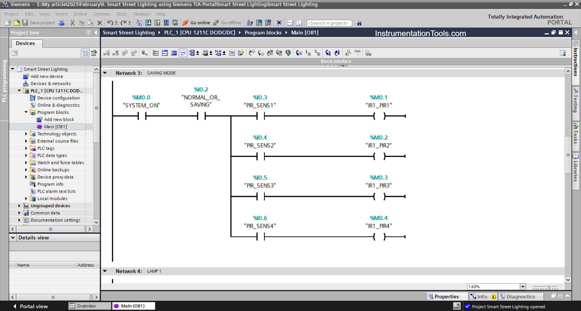
NETWORK 3 (SAVING MODE)
In this network, memory bit IR1_PIR1 (M0.1) will be in HIGH state if contact NO of memory bit SYSTEM_ON (M0.0), selector switch NORMAL_OR_SAVING (I0.2), and sensor PIR_SENS1 (I0.3) are in HIGH state.
The memory bit IR1_PIR2 (M0.2) will be in the HIGH state when the PIR_SENS2 (I0.4) sensor is in the HIGH state.
The memory bit IR1_PIR3 (M0.3) will be in the HIGH state, when the PIR_SENS3 (I0.5) sensor is in the HIGH state.
The memory bit IR1_PIR4 (M0.4) will be in the HIGH state, when the PIR_SENS4 (I0.6) sensor is in the HIGH state.
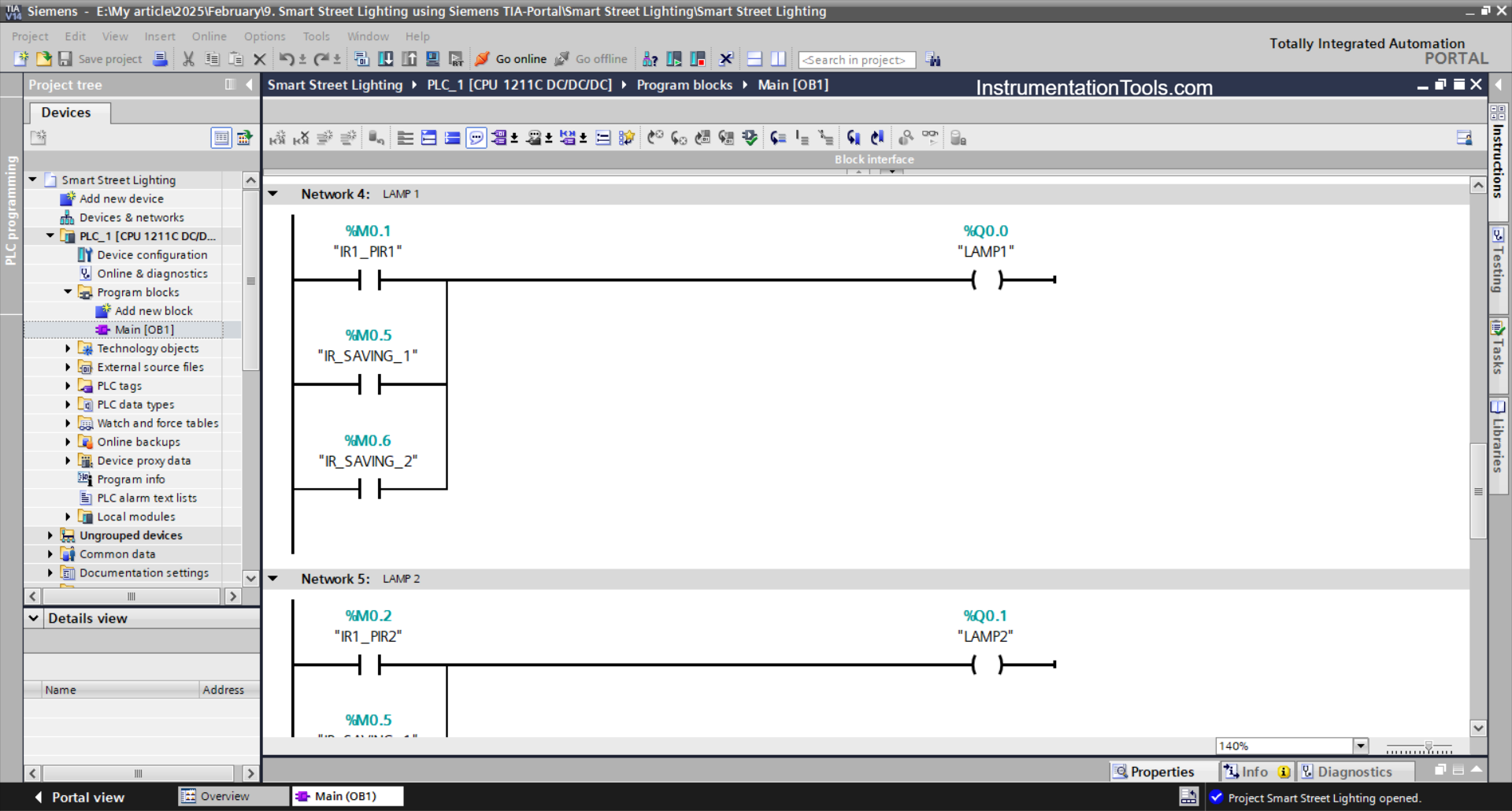
NETWORK 4 (LAMP 1)
If any of the NO contacts of the memory bits IR1_PIR1 (M0.1), IR_SAVING_1 (M0.5), or IR_SAVING_2 (M0.6) are in the HIGH state, then the LAMP1 (Q0.0) output will be ON.
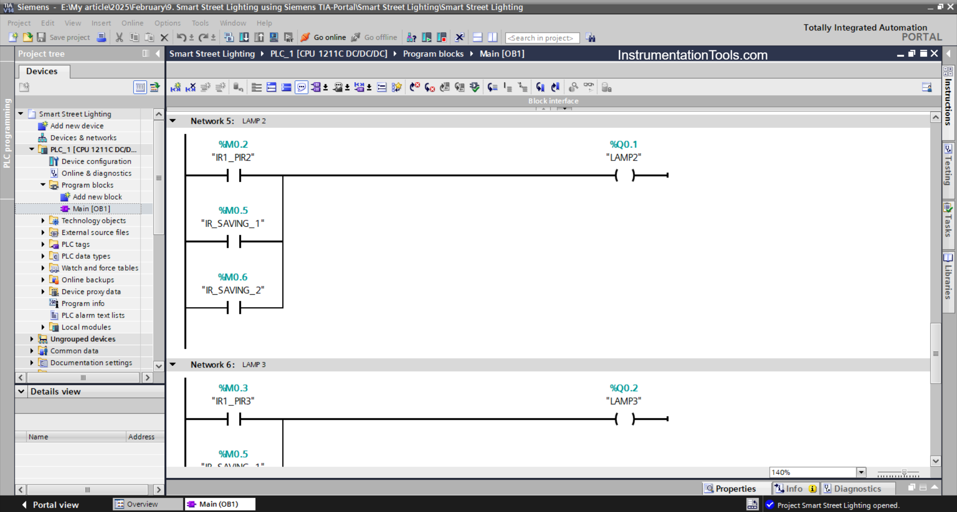
NETWORK 5 (LAMP 2)
If any of the NO contacts of the memory bits IR1_PIR2 (M0.2), IR_SAVING_1 (M0.5), or IR_SAVING_2 (M0.6) are in the HIGH state, then the LAMP2 (Q0.1) output will be ON.
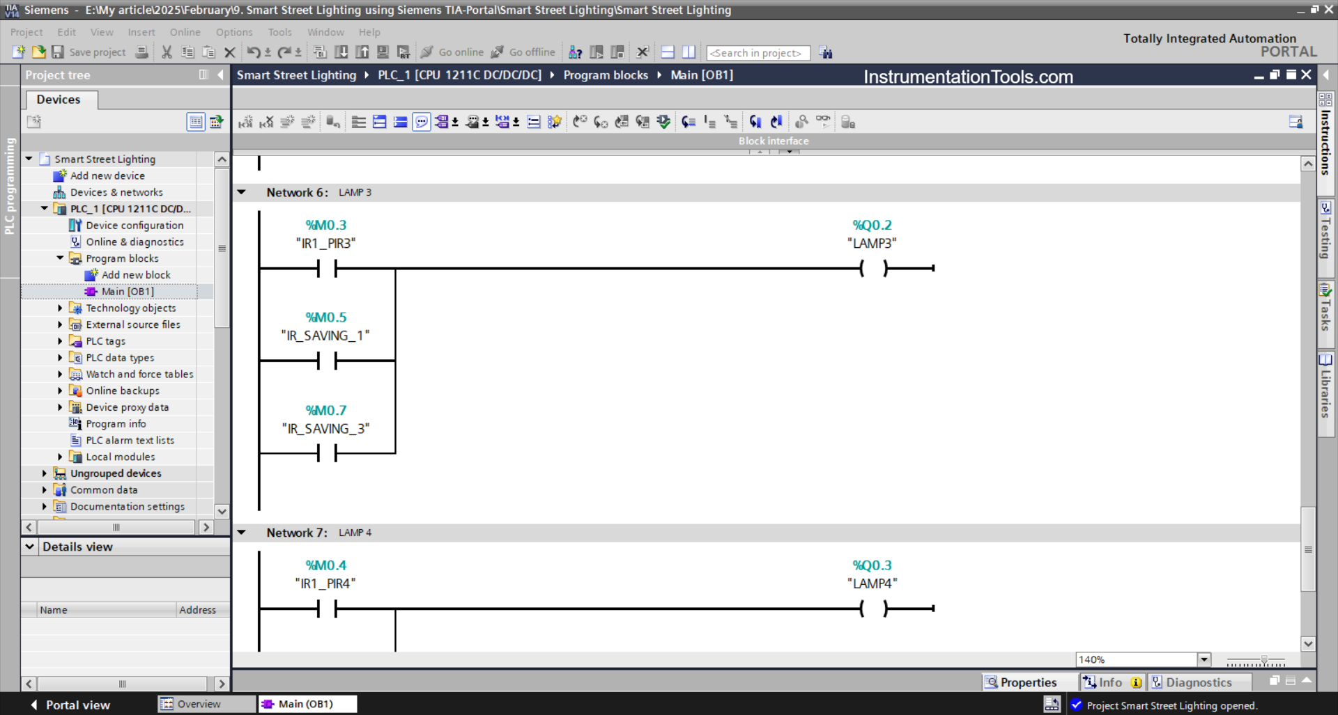
NETWORK 6 (LAMP 3)
If any of the NO contacts of the memory bits IR1_PIR3 (M0.3), IR_SAVING_1 (M0.5), or IR_SAVING_3 (M0.7) are in the HIGH state, then the LAMP3 (Q0.2) output will be ON.
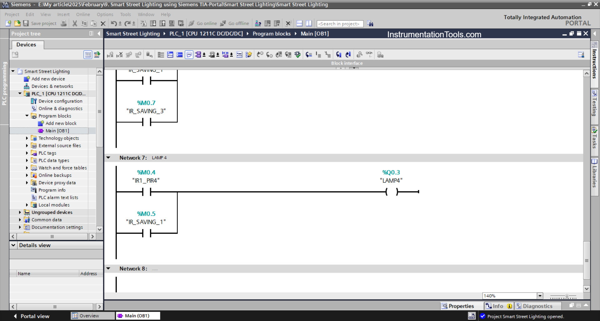
NETWORK 7 (LAMP 4)
When the NO contact of the memory bit IR1_PIR4 (M0.4) or IR_SAVING_1 (M0.5) is in the HIGH state, the output LAMP4 (Q0.3) will be ON.
Read Next:
- PLC Program with Calculation Function
- Purpose of the Marshalling and System Cabinet
- Download GX Works Mitsubishi PLC Software
- Light Auto Control using PLC Programming
- Can a PLC Function Without an HMI or SCADA