In this post, we will learn the most common steps in PLC system design to complete the project efficiently and properly.
PLC is a very important component in industrial automation. PLC comes under the L1 level of industrial automation where it will process the field IOs and work according to the logic written in it. It is thus a very important component because without PLC, you cannot even work in higher levels like cloud networks or IoT; because they cannot work with field devices and get data from them.
So, you have to take care in designing a PLC system properly. There are many procedures, considerations and factors to be considered before choosing the best PLC system.
Try our PLC and SCADA Courses: Register Now
PLC System Design
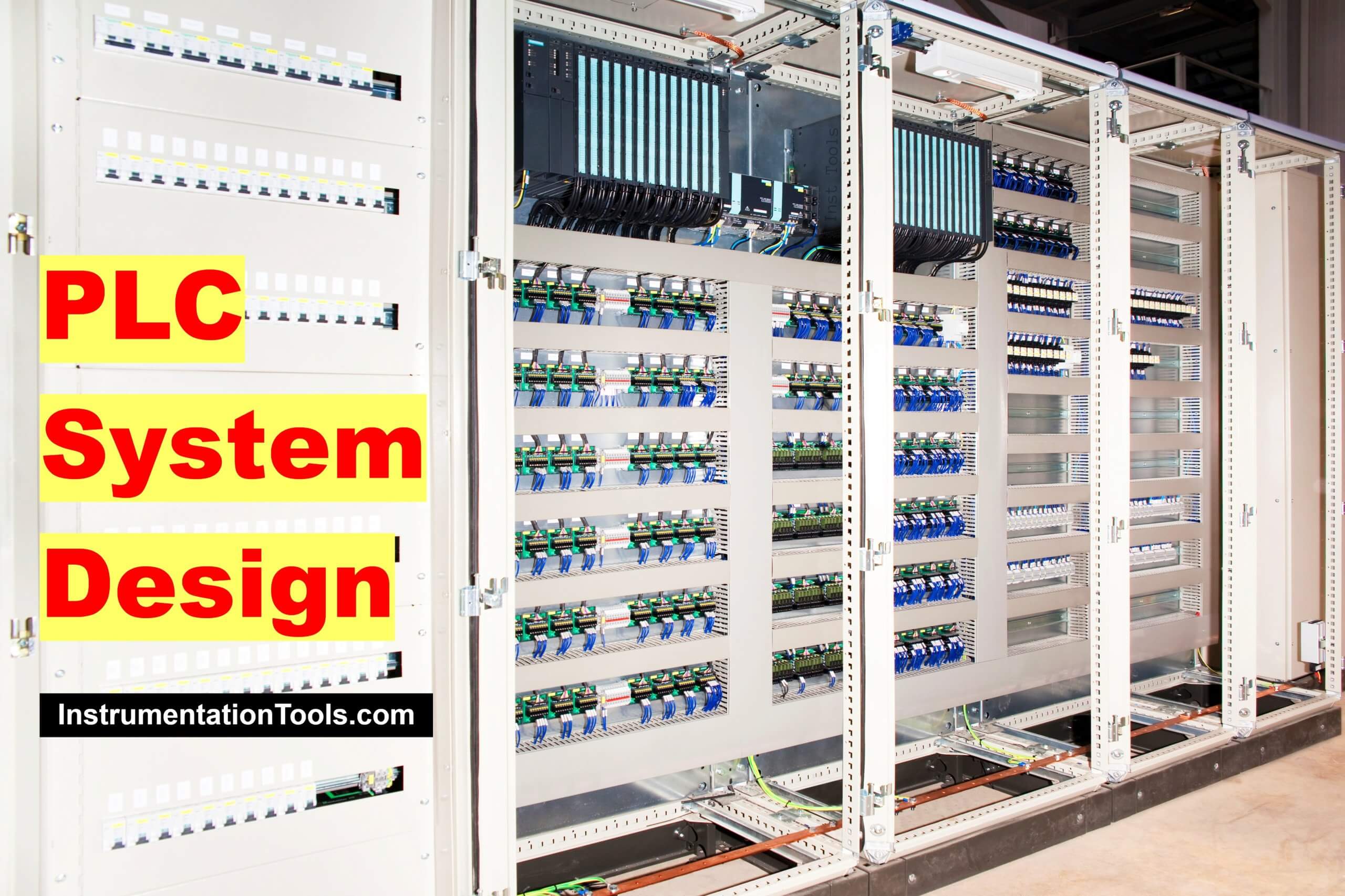
Some of the most common steps which are important in the design of programmable logic controllers are mentioned below.
- Environmental Specifications
- Grounding and Earthing
- Safety Concerns
- Networking
- Field Devices and IO Count
- Proper Grouping of Devices
- Field Wiring Voltage Levels
- Program Complexity and Redundancy
Environmental Specifications
As PLC is an electronic device, it has its share of environmental design constraints. Electronic components are sensitive to environmental effects and utmost care should be taken to see that it does not get damaged due to any abnormal surrounding effect. It must be able to perform to the specifications mentioned in its catalog.
Basic parameters include ambient temperature (operating and storage), relative humidity, operating altitude, and mechanical stress like vibrations majorly. Make sure to see that if you are installing a PLC in a particular area, then it must meet the nearby environment specifications.
If the climate is extremely hot or cold (which means outside the operating range), then choose a hard-rugged PLC which will meet those specifications.
Also, it is not necessary that only a PLC is required in such conditions. You can use additional supporting equipment near it like a fan, air conditioner, heater, or pneumatic cooler; to support it for such conditions.
Grounding and Earthing
Earthing and Grounding are very important criteria in designing a PLC system. It must be noted that improper grounding can result in physical hazards, electrical equipment damage, and worst case, even death.
A PLC has grounding points in its power supply and input and output terminals. When you are installing a PLC in a panel, ensure that the ground is connected at each and every point available.
As there are two types of earthing in a panel – instrument and power, PLC points must be connected to instrument earthing. It must not be connected to power earthing. The voltage between earthing and neutral must be less than 0.5V.
Safety Concerns
PLC is a device that deals with many critical field devices. In terms of safety, there are two types – one which PLC provides and one which PLC must be provided.
A PLC programmer must assign digital outputs for a hooter, fault lamp, tower lamp, and buzzer so that the operator will be alarmed whenever there is a fault. This can help save any untoward incident.
When you are using a PLC, a safety review must be performed at the actual site to see if the PLC will not be impacted by any mechanical, environmental, thermal, electrical, or chemical hazard.
If you go ahead, there is one more advanced device called safety PLC. It has SIL level functionalities that deal with various types of IO safety and programming safety. Safety PLC can detect any permutations and combinations of failures to safely shutdown a system.
Networking
Almost all the PLCs deal with external communications with third-party or same-party devices. As communication provides more flexibility in dealing with data, many protocols are used for communication with field devices, SCADA, etc.
Because communication is sensitive to noise and other electrical disturbances, care must be taken to properly choose its cable with shielding. Also, in such cases, earthing must be very strong to prevent any unwanted noise near it.
Additionally, if you are using Ethernet protocol, it is recommended to provide an Ethernet hub switch in the panel, managed or unmanaged, so that many people can use data from it.
Field Devices and IO Count
When you are choosing a PLC, you must be knowing the number of IOs and field instrument types. It is important to have proper knowledge of the voltage and current required for working with field devices.
Depending on that, you have to choose the required PLC and also the cabling length. Also, consider 20% spare in the IO counts, which will give you flexibility in case of end-time additions in IOs.
If the distance between PLC and the field device is more or if the PLC will be installed in a hazardous area, then install barriers and isolators in the panel. Also, for analog IOs, use proper shielded cables as they are more prone to noise.
Proper Grouping of Devices according to Voltage Level in the PLC Panel
This factor is concerned with panel designing. Make sure to group AC and DC devices like circuit breakers, relays, terminal boards, power supplies, and transformers.
Avoid mixing them in the PLC panel; this means it is not advisable to place a circuit breaker near the PLC. Better keep isolation between devices of the same voltage level. This will also help in troubleshooting and avoiding unwanted performance and noise in the panel.
If AC and DC devices are separated and kept in groups, then the panel also will look more attractive and you can easily identify each and every device properly.
Field Wiring Voltage Levels
In your PLC panel, you are using both AC and DC voltages. If a particular field device is powered by a separate power source, make sure to use its common point for working with it.
Avoid mixing up unwanted common signals with field devices; otherwise, it will either damage the PLC point or will damage the field device.
PLC Program Complexity and Redundancy
If you know the complexity of the PLC program to be developed or if redundancy is required, then choose the PLC accordingly. It must be able to perform in the required scan time, memory and redundancy.
In this way, we understand some general steps in properly designing a PLC system.
If you liked this article, then please subscribe to our YouTube Channel for Instrumentation, Electrical, PLC, and SCADA video tutorials.
You can also follow us on Facebook and Twitter to receive daily updates.
Read Next:
- How to Choose a PLC?
- How to Choose a SCADA?
- Compare PLC and SCADA
- PLC and DCS System Checks
- DCS System Maintenance