Root Cause Analysis (RCA): Yearly 30000 T lost ammonia production reduced to 10000 T due to the steam turbine driven centrifugal compressors due to broken instrument.
| Article Type: | Root Cause Analysis (RCA) |
| Category: | Mechanical |
| Equipment Type: | High Speed, Hi KW Major Rotating Machines |
| Author: | S. Raghava Chari |
Note: This root cause analysis (RCA) is from real-time scenarios that happened in industries during the tenure of one or two decades ago. These articles will help you to improve your troubleshooting skills and knowledge.
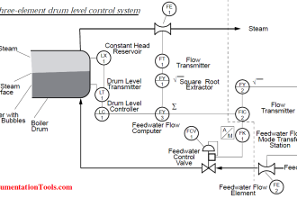
Steam Turbine Driven Centrifugal Compressors Leak Problem
15-25 MW 10000 RPM Steam Turbine Driven Synthesis gas (SG) centrifugal compressors K-601 are ammonia plants rotating machines’ kings.
After a broken instrument process lead connection spill caused, a vicinity fire incident, K-601 third barrel discharge head leaked and it increased progressively.
The crew installed steam ring diluted the synthesis gas (75% H2, 25% N2) leaks and prevented fire hazards.
At shift-wise monitored vicinity environs combustibles readings reaching unacceptable levels, the plant scheduled a shutdown to stop the leaks.
Leaks stopping required changing the O‑Ring and Backup Ring Set (ORBRS) that seals the leaks. It was a 10-days shutdown task. The three monthly leaks stopping robbed 40 on stream days yearly and 30000 Tons ammonia production.
In addition, the plant continued operating the upstream plants at as low loads as practical as starting these after a shutdown (S/D) it takes time, thermally stresses the equipment, and reduces their lives.
Root Cause Analysis Solution
The Rotating Machines Crew’s below-given way of doing the job was the reason for the 10-days plant shutdown (SD) reason:
- Shift the HP case – the crew felt 30 T weight HP case shifting was necessary based on a wrong belief of lack of space between the IP and HP cases to slide out the discharge head. As the available hired crane could lift only 20 T, they decided shifting the Intermediate Pressure Case (IPC). The crane owner and driver had to be pressured into this as they feared even 20 T lift was too heavy for the very old crane.
- IPB shifting involves:
- Open 10” 1500 # RTJ flanged suction and delivery pipes i.e., two large high pressure flanges
- Cut few ¾” and 1” gas and oil lines to move the IPB
- Undo the LP to IP and IP to HP shaft couplings
- Lift and position the IPB ½ m away using the crane
- Unlock split rings, and pull the DH using the chain pulley block arranged before the SD
- Change the Discharge Head ORBRS
- Assemble back the DH
- Position the IPC using the crane
- Align IPC to HPC and LPC
These numerous heavy jobs led to the each time 10-days plant shutdown (SD).
The Author’s 2 days only shut down the ORBRS change method explained below.
The Author’s 8 Days Shutdown Saver Method
The author then instrument engineer feeling guilty of an instrument line leak causing the problem looked for task time cutting ways.
He by few measurements was certain of doing the job in 1½ to 2-days as under:
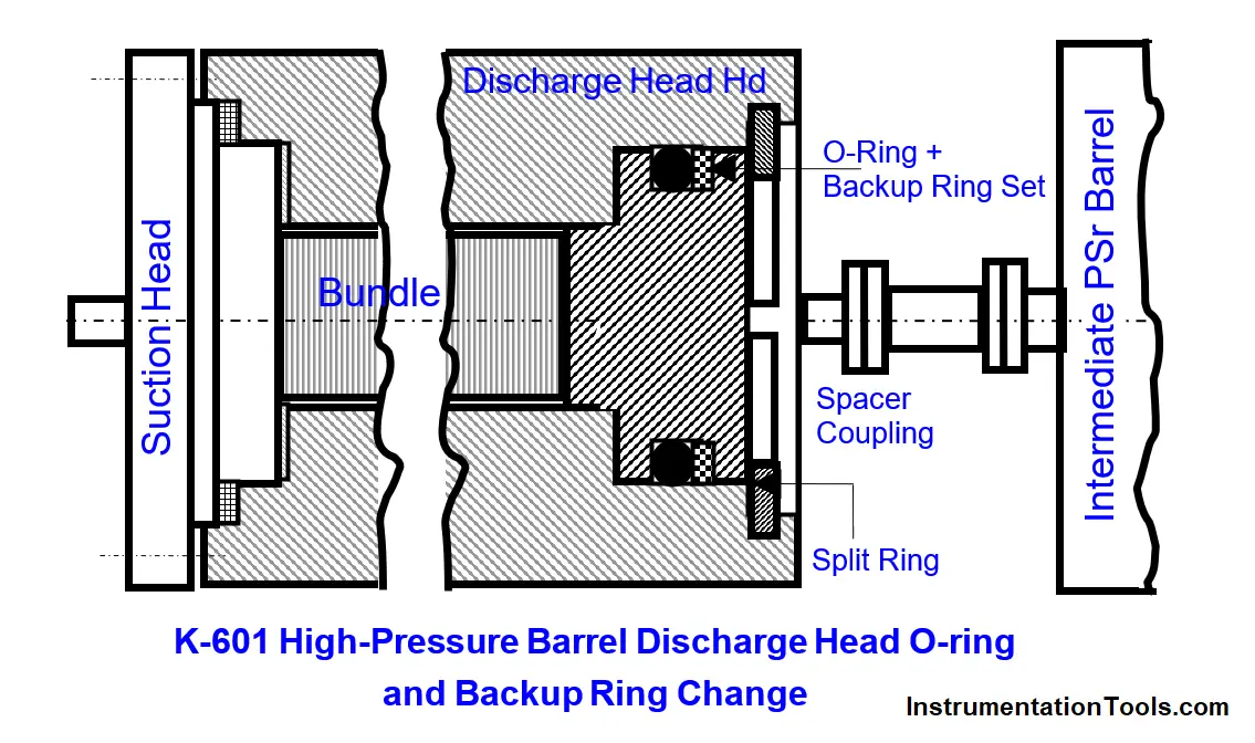
- Shift no compressor barrels! The 600 mm long spacer coupling between IPB and HPB offers enough space to move the DH towards IPB. Taking advantage of this slide out the DH as far as possible from the HPC
- By skillful manipulation one can insert the ORBRS and slide it into the DH grove
- The now done few small-bore pipelines cutting and welding back is not necessary as no barrel is shifted
- No barrel shift; hence no hired crane. Pre shutdown located simple chain pulley block suffices to slide out the DH
- Job would be over in 1½ – 2 days not in 10-days
Perhaps, the projected enormous 8½ days time saving each time and so many other benefits seemed too good to be true to the mindset compressor crew.
Ridiculing the author, the crew, and the then maintenance manager an electrical graduate rejected the author’s offer to get the jobs done and stuck to the 10-days routine!
The job was done in less than 36 hours:
The author became Maintenance Manager three years later. The rotating machine crew under his guidance and using the author’s procedure changed the ORBRS in < 36 hours.
The New Procedure Benefits
The new procedure benefits are:
1. No IPC or any case lift eliminates the following:
- No poor condition crane positioning in the pipe rack obstructing difficult to maneuver area
- No IPB lift and placing back and associated extreme stress the crew and managers felt till the IPB lift and placing back were complete because of the cranes very old condition and the crane driver and owner lacking confidence
- No high pressure large flanges breaking, making and new gaskets use
- No anxieties of likely flange leaks, likely fires and making joints again and new gaskets use
- No difficult complex and time taking IPB to HPB and IPB to LPB thermal growth compensating alignment
2. No 10-days wasteful and exorbitant crane rent payment for just a few hours use
3. No living with the hazardous leaks until the crane availability
4. Most important: 4*8½=34 days less plant outage yearly, 85% less wasteful RFG venting during the shutdown, and its enormous financial savings
5. Last but not least 17% higher ammonia, urea, and NPK fertilizers production.
This Case Study Take outs
Below are these Case Study Take outs:
- Consider alternative methods when the developed procedure involves expensive resources use and very high total plant downtimes.
- Don’t reject other disciplines persons suggestions right away; consider these showing genuine interest, mindset and prejudice free and encourage them; in case their suggestions posed few practical difficulties work together and iron out.
Also Read: Discharge Head 3‑monthly leaks
Author: S. Raghava Chari
Do you face any similar issues? Share with us through the below comments section.
If you liked this article, then please subscribe to our YouTube Channel for Instrumentation, Electrical, PLC, and SCADA video tutorials.
You can also follow us on Facebook and Twitter to receive daily updates.
Read Next: