Control valves are mechanical devices with moving parts, and as such they are subject to friction, primarily between the valve stem and the stem packing.
Some degree of friction is inevitable in valve packing (Note) and in some types of trim where components must move past each other throughout the full range of valve stem travel (e.g. cage-guided globe valves, rotary ball valves), and the goal is to minimize friction to a bare minimum while still maintaining a pressure-tight seal.
Note : Bellows seals are theoretically frictionless, but in practice bellows seals are almost always combined with standard packing to prevent catastrophic blow-out in the event of the bellows rupturing, and so the theoretical advantage of low friction is never realized.
Control Valves Mechanical Friction
In physics, friction is classified as either static or dynamic. Static friction is defined as frictional force holding two stationary objects together.
Dynamic friction is defined as frictional force impeding the motion of two objects sliding past each other. Static friction is always greater in magnitude than dynamic friction.
Anyone who has ever pulled a sled through snow or ice knows that more force is required to “break” the sled loose from a stand-still (static friction) than is required to keep it moving (dynamic friction).
The same holds true for friction in a control valve: the amount of force required to initially overcome static friction (i.e. initiate valve stem motion) usually exceeds the amount of force required to maintain the valve stem in motion.
The presence of friction in a control valve increases the force necessary from the actuator to cause valve movement. If the actuator is electric or hydraulic, the only real problem with increased force is the additional energy required from the actuator to move the valve (recall that mechanical work is the product of force and parallel displacement). If the actuator is pneumatic, however, a more serious problem arises from the combined effects of static and dynamic friction.
A simple “thought experiment” illustrates the problem. Imagine an air-to-open, sliding-stem control valve with the lower bench-set pressure applied to the pneumatic actuator.
This should be the amount of pressure where the valve is just about to open from a fully-closed position. Now imagine slowly increasing the air pressure applied to the actuator. What should this valve do? If the spring tension is set properly, and there is negligible friction in the valve, the stem should smoothly rise from the fully-closed position as pressure increases beyond the bench-set pressure.
However, what will this valve do if there is substantial friction present in the valve assembly? Instead of the stem smoothly lifting immediately as pressure exceeds the bench-set value, this valve will remain fully closed until enough extra pressure has accumulated in the actuator to generate a force large enough to overcome spring tension plus valve friction.
Then, once the stem “breaks free” from static friction and begins to move, the stem will begin to accelerate because the actuator force now exceeds the sum of spring tension and friction, since dynamic friction is less than static friction. Compressed air trapped inside the actuator acts like a spring of its own, releasing stored energy.
As the stem moves, however, the chamber volume in the diaphragm or piston actuator increases, causing pressure to drop, which causes the actuating force to decrease.
When the force decreases sufficiently, the stem stops moving and static friction “grabs” it again. The stem will remain stationary until the applied pressure increases sufficiently again to overcome static friction, then the “slip-stick” cycle repeats.
If we graph the mechanical response of a pneumatic actuator with substantial stem friction, we see something like this:

What should be a straight, smooth line is reduced to a series of “stair-steps” as the combined effect of static and dynamic friction, plus the dynamic effects of a pneumatic actuator, conspire to make precise stem positioning nearly impossible. This effect is commonly referred to as stiction.
Even worse is the effect friction has on valve position when we reverse the direction of pressure change. Suppose that after we have reached some new valve position in the opening direction, we begin to ramp the pneumatic pressure downward.
Due to static friction (again), the valve will not immediately respond by moving in the closed direction. Instead, it will hold still until enough pressure has been released to diminish actuator force to the point where there is enough unbalanced spring force to overcome static friction in the downward direction.
Once this static friction is overcome, the stem will begin to accelerate downward because (lesser) dynamic friction will have replaced (greater) static friction.
As the stem moves, however, air volume inside the actuating diaphragm or piston chamber will decrease, causing the contained air pressure to rise.
Once this pressure rises enough that the stem stops moving downward, static friction will again “grab” the stem and hold it still until enough of a pressure change is applied to the actuator to overcome static friction.
What may not be immediately apparent in this second “thought experiment” is the amount of pressure change required to cause a reversal in stem motion compared to the amount of pressure change required to provoke continued stem motion in the same direction.
In order to reverse the direction of stem motion, not only does the static friction have to be “relaxed” from the last movement, but additional static friction must be overcome in the opposite direction before the stem is able to move that way.
We may clarify this concept by applying the problem-solving strategy of adding numerical quantities to the thought experiment. Suppose we have a control valve with a static packing friction of 50 pounds in either direction, and a diaphragm with a 12-inch diameter (113.1 square inches of area).
According to the force/pressure/area formula (F = PA), an applied pressure of 0.442 PSI will be required to overcome this static friction in either direction.
That is to say, when moving in the upward direction, we must apply 0.442 PSI more pressure than is ideally required to achieve any given valve position. If after achieving this stem position we desire to move the valve downward to some new stem position, we must not only decrease the pressure by 0.442 PSI to relax the tension on the packing, but we must also decrease it another 0.442 PSI to overcome packing friction in the downward direction before the valve moves at all from its last position.
Thus, a pressure reversal of 0.884 PSI (i.e. twice the equivalent value of packing friction) is required to make the valve reverse its direction of motion. This constitutes “deadband” in the control valve’s action, which degrades control behavior.
Thus, the effects of friction on a pneumatic control valve actuator may be quantified by subjecting the valve to small reversals in applied actuator pressure and measuring the resulting stem position.
The largest increment of actuator pressure reversal resulting in zero stem motion represents the total amount of friction within the valve mechanism.
The following graph shows such a test, plotting actuator pressure over time as well as valve stem position over time.
As the actuator pressure is stepped up and down in successively smaller intervals, the control valve’s stem position is seen to respond with less and less motion until it fails to respond at all:

Short of rebuilding a “sticky” control valve to replace damaged or worn components, there is not much that may be done to improve valve stiction other than regular lubrication of the packing (if appropriate).
Lubrication is applied to the packing by means of a special lubricator device threaded into the bonnet of the valve:

As one of the common sources of excessive packing friction is over-tightening of the packing nuts by maintenance personnel eager to prevent process fluid leaks, a great deal of trouble may be avoided simply by educating the maintenance staff on the “care and feeding” of control valve packing for long service life.
Many modern digital valve positioners have the ability to monitor the drive force applied by an actuator on a valve stem, and correlate that force against stem motion. Consequently, it is possible to perform highly informative diagnostic tests on a control valve’s mechanical “health,” at least with regard to friction (Note).
For pneumatic and hydraulic actuators, actuator force is a simple and direct function of fluid pressure applied to the piston or diaphragm.
For electric actuators, actuator force is an indirect function of electric motor current, or may be directly measured using load cells or springs and displacement sensors in the gear mechanism.
Note : Other measures of a control valve’s mechanical status, such as flow capacity, flow characterization, and seat shut-off, cannot be inferred from measurements of actuator force and stem position.
The following valve signature illustrates the kind of diagnostic “audit” that may be obtained from a digital control valve positioner based on actuator force (pneumatic air pressure) and stem motion:

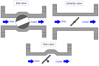
This same diagnostic tool is useful for detecting trim seating problems in valve designs where there is sliding contact between the throttling element and the seat near the position of full closure (e.g. gate valves, ball valves, butterfly valves, plug valves, etc.).
The force required to “seat” the valve into the fully-closed position will naturally be greater than the force required to move the throttling element during the rest of its travel, but this additional force should be smooth and consistent on the graph.
A “jagged” force/travel graph near the fully-closed position indicates interference between the moving element and the stationary seat, providing information valuable for predicting the remaining service life of the valve before the next rebuild.


Many thanks