Inst ToolsInst ToolsInst Tools
  • Courses
  • Automation
    • PLC
    • Control System
    • Safety System
    • Communication
    • Fire & Gas System
  • Instrumentation
    • Design
    • Pressure
    • Temperature
    • Flow
    • Level
    • Vibration
    • Analyzer
    • Control Valve
    • Switch
    • Calibration
    • Erection & Commissioning
  • Interview
    • Instrumentation
    • Electrical
    • Electronics
    • Practical
  • Q&A
    • Instrumentation
    • Control System
    • Electrical
    • Electronics
    • Analog Electronics
    • Digital Electronics
    • Power Electronics
    • Microprocessor
Search
  • Books
  • Software
  • Projects
  • Process
  • Tools
  • Basics
  • Formula
  • Power Plant
  • Root Cause Analysis
  • Electrical Basics
  • Animation
  • Standards
  • 4-20 mA Course
  • Siemens PLC Course
Reading: D.C Tachogenerator Principle
Share
Notification Show More
Font ResizerAa
Inst ToolsInst Tools
Font ResizerAa
  • Courses
  • Design
  • PLC
  • Interview
  • Control System
Search
  • Courses
  • Automation
    • PLC
    • Control System
    • Safety System
    • Communication
    • Fire & Gas System
  • Instrumentation
    • Design
    • Pressure
    • Temperature
    • Flow
    • Level
    • Vibration
    • Analyzer
    • Control Valve
    • Switch
    • Calibration
    • Erection & Commissioning
  • Interview
    • Instrumentation
    • Electrical
    • Electronics
    • Practical
  • Q&A
    • Instrumentation
    • Control System
    • Electrical
    • Electronics
    • Analog Electronics
    • Digital Electronics
    • Power Electronics
    • Microprocessor
Follow US
All rights reserved. Reproduction in whole or in part without written permission is prohibited.
Inst Tools > Blog > Common > D.C Tachogenerator Principle

D.C Tachogenerator Principle

Last updated: April 1, 2018 12:01 pm
Editorial Staff
Common
No Comments
Share
2 Min Read
SHARE

The D.C Tachogenerators is a type of electrical type’s tachogenerators which can also be used for speed measurement.

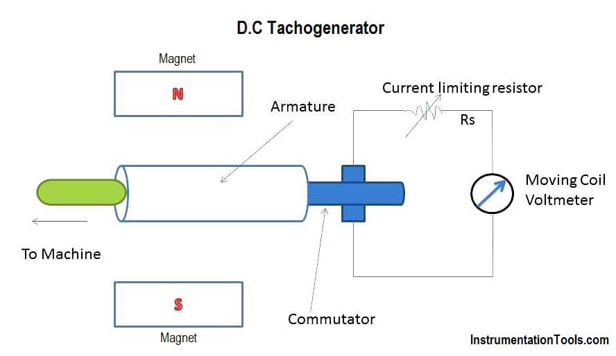
The D.C tachogenerator is shown in below figure.

The armature of the D.C Tachogenerator is kept in the permanent magnetic field. The armature of the tachogenerator is coupled to the machine whose speed is to be measured. When the shaft of the machine revolves, the armature of the tachogenerator revolves in the magnetic field producing e.m.f. which is proportional to the product of the flux and speed to be measured.

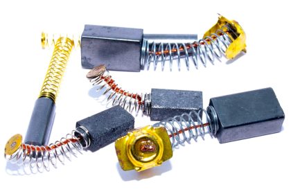
Now as the field of the permanent field is fixed, the e.m.f generated is proportional to the speed directly. The e.m.f induced is measured using moving coil voltmeter with uniform scale calibrated in speed directly. The series resistance is used to limit the current under output short circuit condition. The polarity of output voltage indicates the direction of rotation. The commutator collects current from armature conductors and converts internally induced a.c e.m.f into d.c (unidirectional) e.m.f. while the brushes are used to collect current from commutator and make it available to external circuitry of the d.c tachogenerator.
D.C Tachogenerator Principle

Advantages

The advantages of d.c tachogenerator are as follows:

1.The output voltage is small enough to measure it with conventional d.c voltmeters.
2.The polarity of output voltage directly indicates the direction of rotation.

Disadvantages

The Disadvantages of d.c tachogenerator are as follows:

1.Because of variations in contact resistance, considerable error is introduced in the output voltage. Hence periodic maintenance of the commutator and brushes is required.

2.Non-linearity in the output of the d.c tachogenerator occurs because of distortions in the permanent magnetic field due to large armature currents. Hence input resistance of meter should be very high as compared to the output resistance of the generator.

Don't Miss Our Updates
Be the first to get exclusive content straight to your email.
We promise not to spam you. You can unsubscribe at any time.
Invalid email address
You've successfully subscribed !

Continue Reading

An Overview of Metrology Tools for CNC Machining
What is a Displacement Transducer? – Types and Advantages
Introduction to Urea Bagging Machine
How to Do Linear Programming in Excel?
Measurement Unit Conversions
Custom CNC Machining – A Complete Guide You Cannot Miss
Share This Article
Facebook Whatsapp Whatsapp LinkedIn Copy Link
Share
Leave a Comment

Leave a Reply Cancel reply

Your email address will not be published. Required fields are marked *

Stay Connected

128.3kFollowersLike
69.1kFollowersFollow
208kSubscribersSubscribe
38kFollowersFollow

Categories

Explore More

NPT Connection Measurement Size
What’s the Best GPS Fleet Tracking Software and Systems?
Good and Bad Wiring Practices
8 Data Protection Tips For Businesses And Individuals
How are Data Centers Cooled?
Pneumatic Instrumentation
Applications of Robots in Various Fields
Deep Hole Drilling Ideal Methods For CNC Machining

Keep Learning

IPv4 vs IPv6 - What’s the Difference Between IP addresses

IPv4 vs IPv6 – What’s the Difference Between IP addresses?

Embedded Systems

Introduction to Embedded Systems – Features, Types, Applications

Discrete Manufacturing Automation

Discrete Manufacturing Automation

Difference between Radio Waves and Microwaves

Difference between Radio Waves and Microwaves

What is Zero Trust Security

How a Single ZTNA Solution Can Help Overcome Cybersecurity Issues?

HVAC Questions & Answers

HVAC Questions & Answers

Difference Between Skin Effect and Proximity Effect

Difference Between Skin Effect and Proximity Effect

Difference between IP Address and MAC Address

Difference between IP Address and MAC Address

Learn More

Transmission Lines Protection Questions Answers

Transmission Lines Protection Questions Answers

IEC 61508

What is IEC 61508 ?

CEMS Classification

CEMS Principle, Types, Advantages, and Disadvantages

Three-Phase Power Supply

Single Phase versus Three Phase Power

Pressure Gauge Installation

Pressure Gauge Installation at Pump Discharge

Temperature Sensors Questions

Questions on Thermocouple and Pyrometer

Communicating Delta PLC Software to Simulator

SMART Transmitters Block Diagram

Smart Transmitters LRV & URV

Follow US
All rights reserved. Reproduction in whole or in part without written permission is prohibited.
Welcome Back!

Sign in to your account

Username or Email Address
Password

Lost your password?