Learn how to implement a Star-Delta System using one button in this Schneider PLC Example Program using rising and falling edge functions.
Star-Delta System
This PLC Program uses the Rising Edge and Falling Edge functions in the PLC programming logic.
Contacts that use the Rising Edge function will be Active when the given Input signal changes from a LOW state to a HIGH state.
Contacts that use the Falling Edge function will be Active when the given Input signal changes from a HIGH state to a LOW state.
How This PLC Program Works?
The PLC program only uses 1 button TRIGGER_BUTTON (I0.0) which is used to Turn ON the system and Turn OFF the system.
This PLC system has 3 states:
State-1: When the TRIGGER_BUTTON (I0.0) button is Pressed once, State-1 will Run and the system will be ON.
State-2: When the TRIGGER_BUTTON (I0.0) button is Released, State-2 will Run and Activate the auxiliary contact memory bit IR_1 (M1).
State-3: When the TRIGGER_BUTTON (I0.0) button is Pressed a second time, State-2 will Run and the system will turn OFF.
State-1
In this state, the TRIGGER_BUTTON (I0.0) button uses a NO contact Rising Edge type, so that the memory bit SYSTEM_ON (M0) changes to the HIGH state when the TRIGGER_BUTTON (I0.0) button changes from LOW to HIGH or when the button is Pressed.
State-2
In this state, the TRIGGER_BUTTON (I0.0) button uses a NO contact Falling Edge type, so that the memory bit IR_1 (M1) changes to the HIGH state when the TRIGGER_BUTTON (I0.0) button changes from HIGH to LOW or when the button is Released.
State-3
When the TRIGGER_BUTTON (I0.0) button is Pressed again, the system will be OFF. Because the memory bit IR_2 (M2) is used as an interlock to Turn OFF the memory bit SYSTEM_ON (M0).
When the memory bit SYSTEM_ON (M0) changes to the HIGH state, the Output STAR_MODE (Q0.0) will be ON and the system will Run in STAR mode.
After 5 seconds the system will change to DELTA mode, Output DELTA_MODE (Q0.1) becomes ON, and Output STAR_MODE (Q0.0) changes to OFF.
Program IO Details
| Comment | Input (I) | Output (Q) | TIMER | Word Memory |
| TRIGGER_BUTTON | I0.0 | |||
| STAR_MODE | Q0.0 | |||
| DELTA_MODE | Q0.1 | |||
| SYSTEM_ON | M0 | |||
| IR_1 | M1 | |||
| IR_2 | M2 | |||
| IR_TIMER_CUTOFF | M3 | |||
| TIMER_CUTOFF | TM0 |
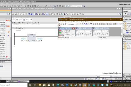
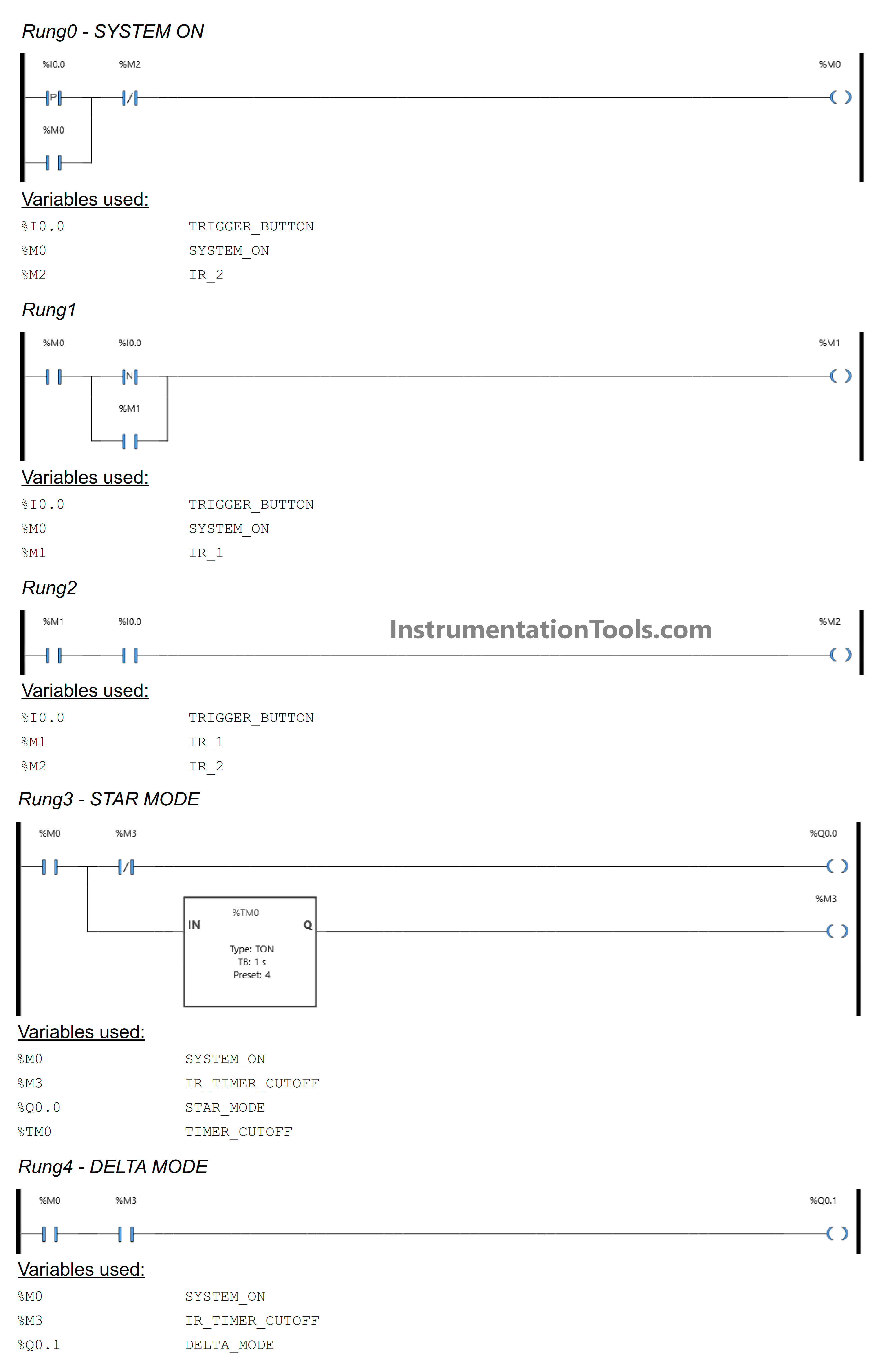
Schneider PLC Example Program
RUNG 0 (SYSTEM ON)
In this Rung, the memory bit SYSTEM_ON (M0) will be in a HIGH state when the TRIGGER_BUTTON (I0.0) button is Pressed. Even though the TRIGGER_BUTTON (I0.0) button is only Active for a moment, the memory bit SYSTEM_ON (M0) remains in the HIGH state because it uses Latching.
When the NC contact of the memory bit IR_2 (M2) is in the HIGH state, the memory bit SYSTEM_ON (M0) will be changed to a LOW state.
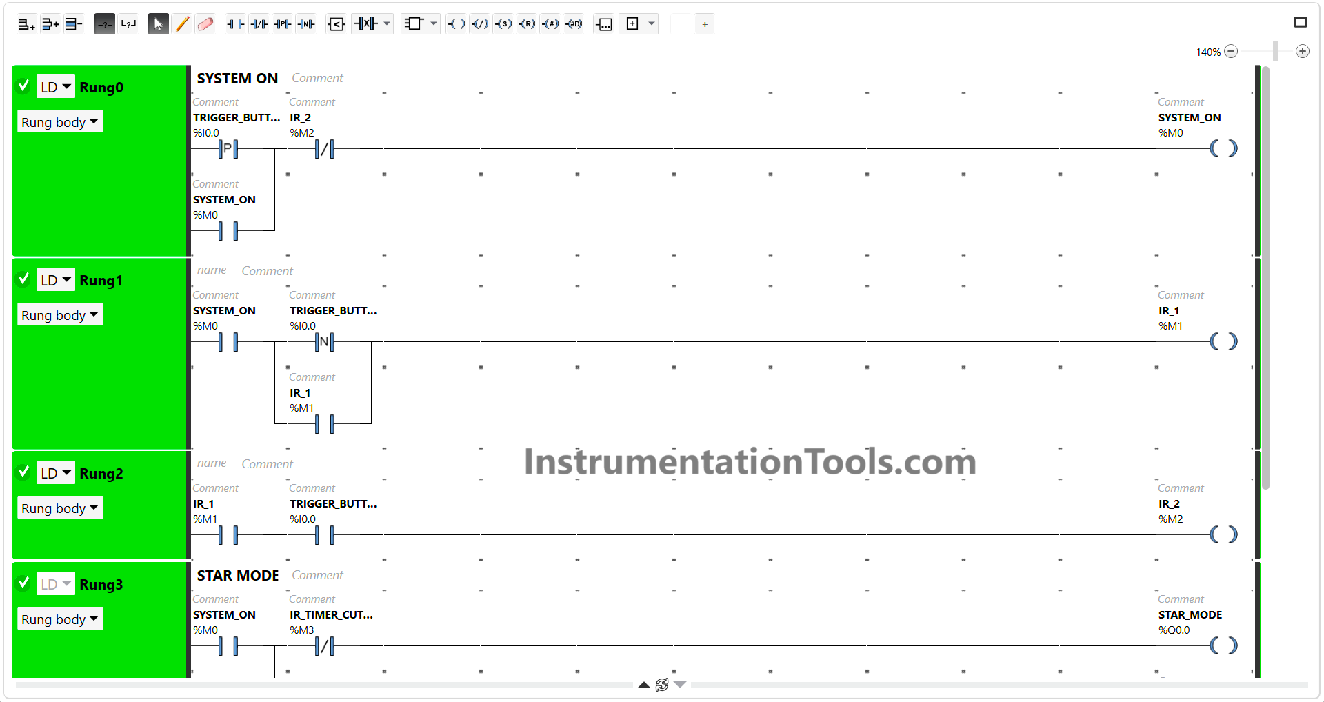
RUNG 1
In this Rung, the memory bit IR_1 (M1) will be in the HIGH state when the NO contact of the memory bit SYSTEM_ON (M0) in the HIGH state and the TRIGGER_BUTTON (I0.0) button is Released.
Even though the TRIGGER_BUTTON (I0.0) button is only Active for a moment, the memory bit IR_1 (M1) remains in the HIGH state because it uses Latching.
RUNG 2
When the NO contact of memory bit IR_1 (M1) is in the HIGH state and the TRIGGER_BUTTON (I0.0) button is Pressed, the memory bit IR_1 IR_2 (M2) will become in the HIGH state.
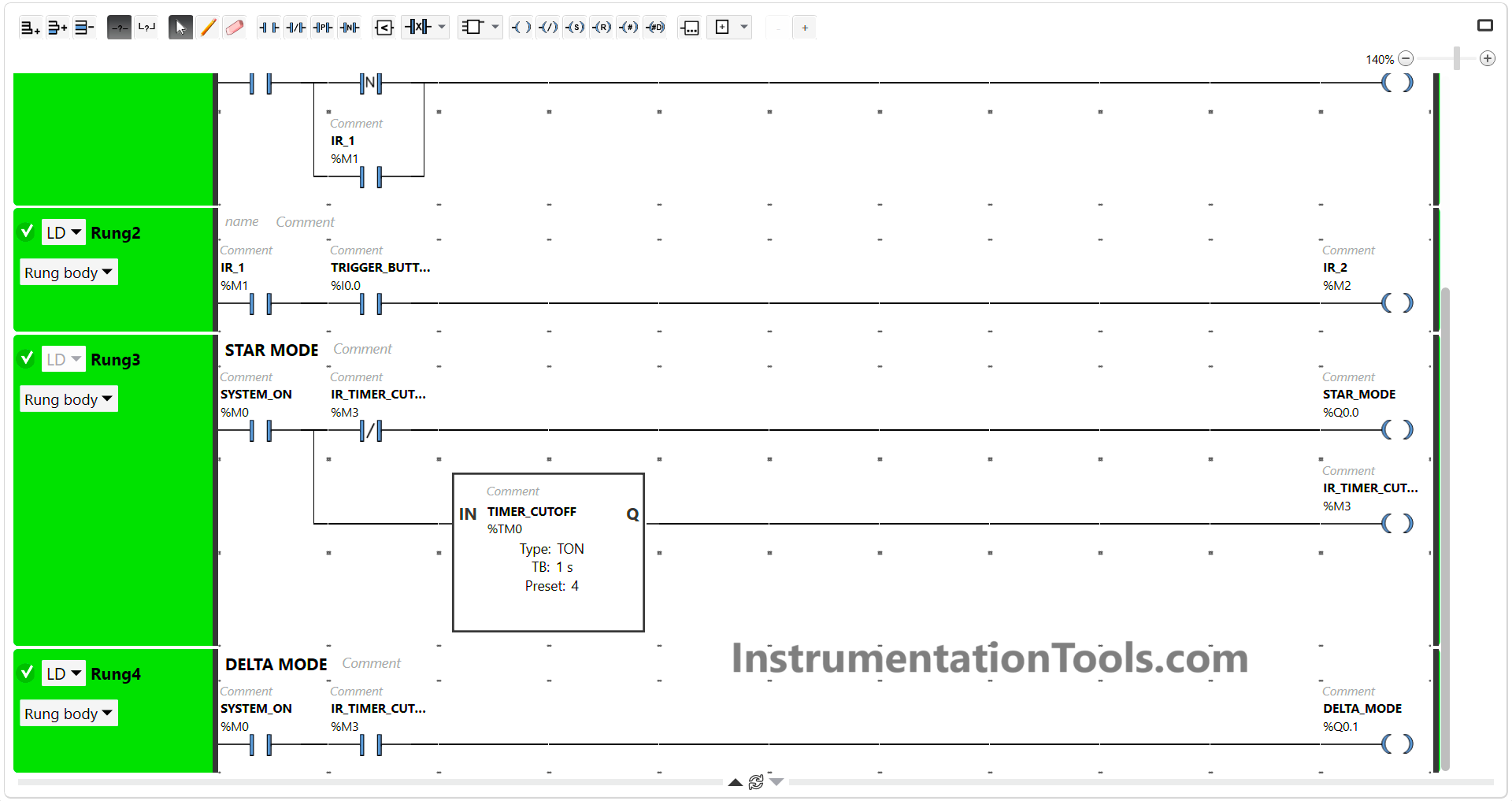
RUNG 3 (STAR MODE)
The STAR_MODE (Q0.0) output will be ON and the timer TIMER_CUTOFF (TM0) Starts counting up to 4 seconds when the NO contact of memory bit SYSTEM_ON (M0) in the HIGH state.
When the timer TIMER_CUTOFF (TM0) finishes counting, the memory bit IR_TIMER_CUTOFF (M3) will become in a HIGH state and the Output STAR_MODE (Q0.0) will become OFF.
RUNG 4 (DELTA MODE)
When the NO contact of memory bit SYSTEM_ON (M0) and IR_TIMER_CUTOFF (M3) is in the HIGH state, the DELTA_MODE (Q0.1) Output will be ON.
Read Next:
- PLC Product Sticker Machine with Weighing
- Perfume Mixing and Filling System PLC Logic
- Waste-Burning System Omron PLC Example
- Product Painting with Omron PLC Program
- Attendance System Program in Omron PLC