Inst ToolsInst ToolsInst Tools
  • Courses
  • Automation
    • PLC
    • Control System
    • Safety System
    • Communication
    • Fire & Gas System
  • Instrumentation
    • Design
    • Pressure
    • Temperature
    • Flow
    • Level
    • Vibration
    • Analyzer
    • Control Valve
    • Switch
    • Calibration
    • Erection & Commissioning
  • Interview
    • Instrumentation
    • Electrical
    • Electronics
    • Practical
  • Q&A
    • Instrumentation
    • Control System
    • Electrical
    • Electronics
    • Analog Electronics
    • Digital Electronics
    • Power Electronics
    • Microprocessor
  • Request
Search
  • Books
  • Software
  • Projects
  • Process
  • Tools
  • Basics
  • Formula
  • Power Plant
  • Root Cause Analysis
  • Electrical Basics
  • Animation
  • Standards
  • 4-20 mA Course
  • Siemens PLC Course
Reading: Solenoid Valve Functional Testing
Share
Notification Show More
Font ResizerAa
Inst ToolsInst Tools
Font ResizerAa
  • Courses
  • Design
  • PLC
  • Interview
  • Control System
Search
  • Courses
  • Automation
    • PLC
    • Control System
    • Safety System
    • Communication
    • Fire & Gas System
  • Instrumentation
    • Design
    • Pressure
    • Temperature
    • Flow
    • Level
    • Vibration
    • Analyzer
    • Control Valve
    • Switch
    • Calibration
    • Erection & Commissioning
  • Interview
    • Instrumentation
    • Electrical
    • Electronics
    • Practical
  • Q&A
    • Instrumentation
    • Control System
    • Electrical
    • Electronics
    • Analog Electronics
    • Digital Electronics
    • Power Electronics
    • Microprocessor
  • Request
Follow US
All rights reserved. Reproduction in whole or in part without written permission is prohibited.
Inst Tools > Blog > Calibration > Solenoid Valve Functional Testing

Solenoid Valve Functional Testing

Last updated: August 29, 2020 12:21 pm
Editorial Staff
Calibration Control Valves Solenoid Valve
4 Comments
Share
2 Min Read
SHARE

Here we are discussing how to check or functional test a solenoid valve using instrument air supply.

Contents
Solenoid Valve TestingTest Equipment:-Typical SOV Test Set-upFunctional Testing Procedure :

Solenoid Valve Testing

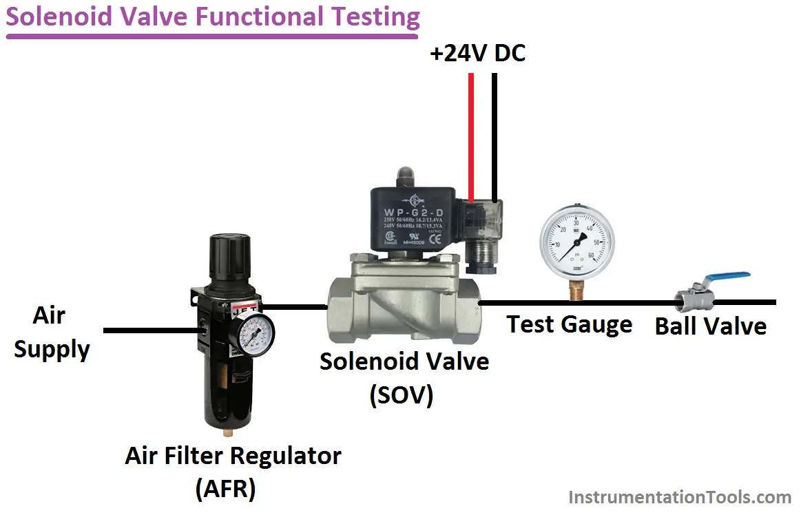
  • The air supply is connected to the Air Filter Regulator (AFR)
  • Set the Required pressure in the AFR and connect the outlet of AFR to Solenoid Valve (SOV)
  • Connect the outlet of Solenoid Valve to a Ball Valve.
  • Connect a Pressure Gauge ( Test Gauge ) at the outlet of Solenoid Valve.
  • Test Gauge’s purpose is to check the pressure in the outlet line depends on SOV energization.
  • Ball valve used to stop the functional testing

Test Equipment:-

  1. Air Filter Regulator
  2. Digital Multimeter (optional)
  3. 24VDC Power Supply
  4. Test Gauge

Typical SOV Test Set-up

Solenoid Valve Functional TestingFunctional Testing Procedure :

a. Check the manufacturer datasheet/instrument nameplate. Confirm the solenoid valve voltage/current ratings (consider it is +24V DC Device in our example)

b. Check the solenoid valve port configuration (i.e. either N.C. or N.0) (Assume it is N.C. in our example )

c. The hook-up instrument as per the typical test set-up shown above.

d. Apply air specified set pressure to inlet port of valve and connect 24VDC to solenoid valve terminals.

e. Switch on power supply 24VDC, check the valve energize by monitoring the test gauge pressure (Pressure will increase)

f. Switch off the supply. and confirm the valve de-energized, check test gauge pressure again (Pressure will decrease)

g. Tabulate all results in the Check Sheet.

Also Read: Solenoid Valve Troubleshooting Tips

Read Next:

  • 4-way Solenoid Valve
  • 3-way Solenoid Valve
  • 2-way Solenoid Valve
  • Solenoid Valve Selection
  • Types of Solenoid Valves
Don't Miss Our Updates
Be the first to get exclusive content straight to your email.
We promise not to spam you. You can unsubscribe at any time.
Invalid email address
You've successfully subscribed !

Continue Reading

Gas Valve Sizing
What is a Boiler Pressure Relief Valve?
Automated Block Valve (ABV)
Root Cause Analysis for FRP Line Damaged due to On-Off Valve
Inherent vs Installed Control Valve Flow Characteristics
Solenoid Valve Selection Criteria
Share This Article
Facebook Whatsapp Whatsapp LinkedIn Copy Link
Share
4 Comments
  • Ebikefe Eric George says:
    March 5, 2020 at 7:27 pm

    Helpful information…

    Reply
  • Fred Mitchel says:
    February 22, 2022 at 2:31 am

    Your valve will never close for there is no vent path-

    Reply
  • مهدی says:
    August 29, 2023 at 9:26 am

    The explanation of the diagram was excellent, concise and useful

    Reply
  • Jalal.sad says:
    September 7, 2023 at 10:18 pm

    Very good.
    Thank you

    Reply

Leave a Reply Cancel reply

Your email address will not be published. Required fields are marked *

Stay Connected

128.3kFollowersLike
69.1kFollowersFollow
210kSubscribersSubscribe
38kFollowersFollow

Categories

Explore More

Smart Transmitters LRV & URV
Basics of Globe Valves
Complementary Control Valve Sequence
Uncertainty Calculations of Pressure Calibration
What is Complementary Split Range Control (CSRC)?
Cavitation Test Setup
Refrigeration Compressor Turbine Not-tripping when needed Trip
Incident Investigation: Motor Operated Valve Lesson

Keep Learning

Steam conditioning valves

Concept of Steam Conditioning Valves

Valve Interlock

Valve Interlock

How to Test a Pressure Switch ?

How to Test a Pressure Switch ?

Infrared Temperature Calibrators

Different Types of Temperature Calibrators

Pressure Gauge Calibration Procedure

Valve Seat leakage Test

Valve Seat Leakage Test

Needle Valve Body Design

What is Needle Valve ?

Relief Valve

Pressure Relief Valve Principle

Learn More

Displacement Sensing Accelerometer

Seismic Displacement Sensing Accelerometer

Resistance Temperature Detectors Troubleshooting Tips

Resistance Temperature Detectors Troubleshooting Tips

Piezo-electric Acceleration Measuring Device

Piezo-electric Acceleration Measuring Device

Electric Short Circuit

Electric Circuit : Open & Short Circuits

Types of Angular Velocity Measurement

Types of Angular Velocity Measurement

capacitor-filter

Capacitor Filter Working Principle

As-found and As-left Calibration

As-found and As-left Documentation during Calibration

Interview Questions on Transmission & Distribution

Interview Questions on Transmission & Distribution

Menu

  • About
  • Privacy Policy
  • Copyright

Quick Links

  • Learn PLC
  • Helping Hand
  • Part Time Job

YouTube Subscribe

Follow US
All rights reserved. Reproduction in whole or in part without written permission is prohibited.
Welcome Back!

Sign in to your account

Username or Email Address
Password

Lost your password?