A solenoid valve is an electromechanical controlled valve. The valve features a solenoid, which is an electric coil with a movable ferromagnetic core in its center. This core is called the plunger.
In rest position, the plunger closes off a small orifice. An electric current through the coil creates a magnetic field. The magnetic field exerts a force on the plunger.
As a result, the plunger is pulled toward the center of the coil so that the orifice opens. This is the basic principle that is used to open and close solenoid valves.
“A solenoid valve is an electromechanical actuated valve to control the flow of liquids and gases.”
Circuit Functions of Solenoid Valves
Solenoid valves are used to close, dose, distribute or mix the flow of gas or liquid in a pipe. The specific purpose of a solenoid valve is expressed by its circuit function.
A 2/2 way valve has two ports (inlet and outlet) and two positions (open or closed). A 2/2 way valve can be ‘normally closed’ (closed in de-energized state) or ‘normally open’ (open in de-energized state).
A 3/2 way valve has three ports and two positions and can therefore switch between two circuits. 3/2 way valves can have different functions such as normally closed, normally open, diverting or universal. More ports or combinations of valves in a single construction are possible.
The circuit function can be expressed in a symbol. Below are some examples of the most common circuit functions. The circuit function of a valve is symbolized in two rectangular boxes for the de-energized state (right side, visualized by ) and energized state (left). The arrows in the box show the flow direction between the valve ports.
The examples show a 2/2-way Normally Open (NO) valve, a 2/2-way Normally Closed (NC) valve and a 3/2-way Normally Closed valve. For more information about valve symbols and circuit functions, please visit the page about valve symbols.

Type of Operation
Solenoid valves can be categorized into different groups of operation.
Direct operated solenoid valves:
Direct operated (direct acting) solenoid valves have the most simple working principle. The medium flows through a small orifice which can be closed off by a plunger with a rubber gasket on the bottom.
A small spring holds the plunger down to close the valve. The plunger is made of a ferromagnetic material. An electric coil is positioned around the plunger.
As soon as the coil is electrical energized, a magnetic field is created which pulls the plunger up towards the center of the coil. This opens the orifice so that the medium can flow through. This is called a Normally Closed (NC) valve.
A Normally Open (NO) valve works the opposite way: it has a different construction so that the orifice is open when the solenoid is not powered. When the solenoid is actuated, the orifice will be closed.
The maximum operating pressure and the flow rate are directly related to the orifice diameter and the magnetic force of the solenoid valve. This principle is therefore used for relatively small flow rates.
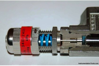
Direct operated solenoid valves require no minimum operating pressure or pressure difference, so they can be used from 0 bar up to the maximum allowable pressure. The displayed solenoid valve is a direct operated, normally closed 2/2 way valve.
 solenoid valves")
Indirect Operated (Servo Or Pilot Operated) solenoid valves:
Indirect operated solenoid valves (also called servo operated, or pilot operated) use the differential pressure of the medium over the valve ports to open and close.
Usually these valves need a minimum pressure differential of around 0.5 bar. The inlet and outlet are separated by a rubber membrane, also called diaphragm. The membrane has a small hole so that the medium can flow to the upper compartment. The pressure and supporting spring above the membrane will ensure that the valve remains closed.
The chamber above the membrane is connected by a small channel to the low pressure port. This connection is blocked in the closed position by a solenoid. The diameter of this “pilot” orifice is larger than the diameter of the hole in the membrane.
When the solenoid is energized, the pilot orifice is opened, which causes the pressure above the membrane to drop. Because of the pressure difference on both sides of the membrane, the membrane will be lifted and the medium can flow from inlet port to outlet port.
The extra pressure chamber above the membrane acts like an amplifier, so with a small solenoid still a large flow rate can be controlled. Indirect solenoid valves can be used only for one flow direction.
Indirect operated solenoid valves are used in applications with a sufficient pressure differential and a high desired flow rate, such as for example irrigation systems, showers or car wash systems. Indirect valves are also known as servo controlled valves.

Semi-Direct Operated solenoid valves:
Semi-direct operated solenoid valves combine the properties of direct and indirect valves. This allows them to work from zero bar, but still they can handle a high flow rate. They look somewhat like indirect valves and also feature a movable membrane with a small orifice and pressure chambers on both sides.
The difference is that the solenoid plunger is directly connected to the membrane. When the plunger is lifted, it directly lifts the membrane to open the valve.
At the same time, a second orifice is opened by the plunger that has a slightly larger diameter than the first orifice in the membrane. This causes the pressure in the chamber above the membrane to drop.
As a result, the membrane is lifted not only by the plunger, but also by the pressure difference. This combination results in a valve that operates from zero bar, and can control relatively large flow rates.
Often, semi-direct operated valves have more powerful coils than indirect operated valves. Semi-direct operated valves are sometimes called assisted-lift solenoid valves.

Direct Operated 3/2 Way Solenoid Valves:
A 3/2 way solenoid valve has three ports and two switching states. In each switching state, two of the three ports are connected. By activating the solenoid, the valve switches state and a different connection between the valve ports is established.
The drawing below shows a direct operated 3/2 way valve. In the de-energized state, the medium can flow between from the port on the right side to the top port. In the energized state, the medium can flow from the left port to the right port. This is a called a normally closed 3/2-way valve.

Solenoid Valve Symbols
Valves can have two or more ports and control the flow of the media between those ports. The circuit function of the valve describes the different switching states it has. For a systematic representation, symbols are used.
Valves are appointed with two numbers, for example a 2/2-way valve. The first number indicates the number of connection ports. The second number is the number of switching states.
A 2/2 way valve has two pipe connections (inlet and outlet) and two switching states (open and closed). The designation Normally Closed (NC) or Normally Open (NO) determines if the valve is closed or open in de-energized state.
A 3/2 way valve has three ports and two switching states. In each switching state, a different port is closed off. More ports and switching states are possible.
Valve Symbols
For each state of the valve, a single square is drawn. A 2/2 valve has two states (open/close) and is therefore represented by two adjacent squares. In each square is shown how the medium can flow between the ports.
This is done with arrows, that indicate which ports are connected and what is the flow direction. Closed ports are indicated by a ‘T’. To indicate which square is active when the solenoid is electrically energized, a little actuator symbol is used on both sides.
On the left a solenoid symbol is used to show that the left square is the energized state. On the right a spring symbol is used for the rest state.

Example: Normally Open 2/2 Way Valve
The major part of the solenoid valves are normally closed 2/2-way valves. This example shows a ‘normally open’ 2/2 way valve. The open and closed state are again displayed with two rectangular squares. It often happens that the actuator symbols (spring and coil) are left away, so it becomes unclear which state is the electrical energized state.
Also pay attention that the left and right square are swapped by some manufacturers. This can lead to confusion, especially when the actuator symbols are left out.

Example: 3/2 Way Valve
3/2-way valves have two positions and three connection ports. These valves can be used for multiple applications, such as switching between two circuits, or actuating a hydraulic cylinder.
The symbols below show different circuit functions of 3/2 way valves.

Also Read: Solenoid Valve with Manual Reset


hai reddy i need ac dc solenoid coil how to find ohm
Why there is both side cut marks in the plunger of SOV.
Good Explanatory method of the Subject .
We suggest if you add the Working Video at same time of Write up By Drawing /Flow Diagram .
I’m thankful you explained to us that a solenoid valve is used to either close, dose, distribute, or mix the flow of gas or liquid in a pipe, depending on the purpose its circuit function is specifically designed for. It seems like my brother needs a new solenoid valve to use for one of the systems in the oil factory he manages, so he’s looking for a replacement to install. I’ll keep this in mind while I help him find a trusted manufacturer to contact about the solenoid valves he needs soon.