Inst ToolsInst ToolsInst Tools
  • Courses
  • Automation
    • PLC
    • Control System
    • Safety System
    • Communication
    • Fire & Gas System
  • Instrumentation
    • Design
    • Pressure
    • Temperature
    • Flow
    • Level
    • Vibration
    • Analyzer
    • Control Valve
    • Switch
    • Calibration
    • Erection & Commissioning
  • Interview
    • Instrumentation
    • Electrical
    • Electronics
    • Practical
  • Q&A
    • Instrumentation
    • Control System
    • Electrical
    • Electronics
    • Analog Electronics
    • Digital Electronics
    • Power Electronics
    • Microprocessor
  • Request
Search
  • Books
  • Software
  • Projects
  • Process
  • Tools
  • Basics
  • Formula
  • Power Plant
  • Root Cause Analysis
  • Electrical Basics
  • Animation
  • Standards
  • 4-20 mA Course
  • Siemens PLC Course
Reading: How Ball Valves Work ?
Share
Font ResizerAa
Inst ToolsInst Tools
Font ResizerAa
  • Courses
  • Design
  • PLC
  • Interview
  • Control System
Search
  • Courses
  • Automation
    • PLC
    • Control System
    • Safety System
    • Communication
    • Fire & Gas System
  • Instrumentation
    • Design
    • Pressure
    • Temperature
    • Flow
    • Level
    • Vibration
    • Analyzer
    • Control Valve
    • Switch
    • Calibration
    • Erection & Commissioning
  • Interview
    • Instrumentation
    • Electrical
    • Electronics
    • Practical
  • Q&A
    • Instrumentation
    • Control System
    • Electrical
    • Electronics
    • Analog Electronics
    • Digital Electronics
    • Power Electronics
    • Microprocessor
  • Request
Follow US
All rights reserved. Reproduction in whole or in part without written permission is prohibited.
Inst Tools > Blog > Control Valves > How Ball Valves Work ?

How Ball Valves Work ?

Last updated: January 23, 2019 11:47 am
Editorial Staff
Control Valves
No Comments
Share
3 Min Read
SHARE

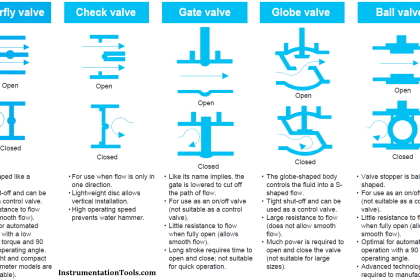
In the Ball Valve design, a spherical ball with a passageway cut through the center rotates to allow fluid more or less access to the passageway.

Contents
ApplicationsAdvantagesDisadvantages

When the passageway is parallel to the direction of fluid motion, the valve is wide open; when the passageway is aligned perpendicular to the direction of fluid motion, the valve is fully shut (closed).

Also Read : Types of Ball Valves

The following set of photographs shows a hand-operated ball valve in three different positions, from nearly full closed to nearly full open (left to right):

How Ball Valves Work ?

Simple ball valves with full-sized bores in the rotating ball are generally better suited for on/off service than for throttling (partially-open) service.

Also See : Ball Valve Animation

A better design of ball valve for throttling service is the characterized or segmented ball valve, shown in various stages of opening in the following set of photographs:

Ball Valve design

The V-shaped notch cut into the opening lip of the ball provides a narrower area for fluid flow at low opening angles, providing more precise flow control than a plain-bore ball valve.

Applications

  • Ball valves are excellent in chemical applications, including the most challenging services (e.g. dry chlorine, hydrofluoric acid, oxygen).
  • General sizes available are 1/2″ to 12″.
  • Compliant with ASME is the flange rating, either 150, 300, 600, 900# or occasionally higher classes, enabling high performance ball valves to withstand up to 2250 psi.
  • The operating temperature which is primarily dependent on seats and seals may be rated as high as 550°F.
  • Standard valves comply with ASME face-to-face dimensions, making the ball valve easy to retrofit and replace.

Advantages

  • Low cost
  • High flow capacity
  • High pressure/temperature capabilities
  • Low leakage and maintenance
  • Tight sealing with low torque
  • Easy quarter turn operation- desirable to most operators
  • Fairly easy to automate.

Disadvantages

  • Limited throttling characteristics
  • Prone to cavitation
  • Not suitable for slurry applications due to cavities around the ball and seats. Slurries tend to solidify or clog inside the cavities, greatly increasing the operating torque of the valve and in some cases rendering the valve inoperable.

Articles You May Like :

JT Valve Working Principle

What is On/off valve ?

Metal Seated Valves

Control Valve Questions

Split Range Control Valves

Don't Miss Our Updates
Be the first to get exclusive content straight to your email.
We promise not to spam you. You can unsubscribe at any time.
Invalid email address
You've successfully subscribed !

Continue Reading

What is Split Range Control Loop ?
Inherent vs Installed Control Valve Flow Characteristics
ON OFF Valve Preventive Maintenance and Testing Procedure
How Pilot operated Solenoid Valve Works ?
List of Valve Standards
Valve Safety Factor
Share This Article
Facebook Whatsapp Whatsapp LinkedIn Copy Link
Share
Leave a Comment

Leave a Reply Cancel reply

Your email address will not be published. Required fields are marked *

Stay Connected

128.3kFollowersLike
69.1kFollowersFollow
210kSubscribersSubscribe
38kFollowersFollow

Categories

Explore More

Malfunctioning Inlet Check Valves caused chaos at Compressor stop/trip
Types of Control Valve Trim
What is Tilting Disk Check Valve ?
What is Reducing Valve ?
Control Valve Recommended Practices for Harsh Process Conditions
Exclusive Control Valve Sequence
Fundamentals of Valves and their Types
What is Ball Valve ?

Keep Learning

Valve Technician Interview Questions

Valve Technician Interview Questions

Questions and Answers on Valves

Valve Quiz

Flapper nozzle system

What is Flapper Nozzle System ?

Control valve sizing

Relative Flow Capacity of a Valve

Incident Investigation: Motor Operated Valve Lesson

Incident Investigation: Motor Operated Valve Lesson

Control Valves Leakage Classifications

Control Valves Leakage Classifications

Relief Valve

Pressure Relief Valve Principle

Control Valve Relation between Cv and Kv

Control Valve Relation between Cv and Kv

Learn More

Configure Analog Inputs and Outputs in Delta PLC

How to Configure Analog Inputs and Outputs in Delta PLC?

Pressure Manometer

Types of Manometers

Types of Motor Enclosures

Types of Motor Enclosures

What is an Oil Separator in HVAC?

What is an Oil Separator in HVAC?

Preventa XPS MC, XPS MP - Safety controllers

High-end Programmable Logic Controller – Schneider PLC

Bubbler Liquid Level Transmitter Calculation

Bubbler Liquid Level Transmitter Calculation

Calibration of Measuring Instruments

Calibration of Measuring Instruments – Significance, Costs & Risks

Electrical Machines Questions and Answers

Synchronous Machine Quiz

Menu

  • About
  • Privacy Policy
  • Copyright

Quick Links

  • Learn PLC
  • Helping Hand
  • Part Time Job

YouTube Subscribe

Follow US
All rights reserved. Reproduction in whole or in part without written permission is prohibited.
Welcome Back!

Sign in to your account

Username or Email Address
Password

Lost your password?