Control Valve Installation, Maintenance, Disassembly & Reassembly
A. INSTALLATION
1. Valve Body:
Set control valve in the horizontal line of piping in an accessible location with the arrow on the side of the valve body in the direction of fluid flow. Upright positioning of control valve is preferable for ease of maintenance.

Work spaces around the control valve body are to be provided sufficiently for easy removal or reinstall of parts during maintenance.
Caution: Piping systems are to be flushed thoroughly with sufficient amount of water or air prior to installation of control valve body and strainer to prevent possible damage on the internals by foreign materials after commissioning.
2. Strainer:
To be installed between the inlet block valve and control valve. In case other strainer is installed upstream line, this strainer may be deleted.
3. Isolation valves:
Stop valves (and gauges if necessary) in inlet and outlet lines are to be installed to provide means for checking, adjustment or emergency maintenance during operation.
4. Bypass valve:
Set a bypass around the control valve for emergency use when the control valve needs to be isolated.
5. Air tubing:
Connect air tubing between the controller and diaphragm actuator or the valve positioner (if one is in use). Maximum allowable operating pressure for diaphragm actuators is 4 kg/cm² (60 psig).
6. Piping for large pressure drop:
Recommended piping for the compressible fluids with large pressure drop (control valve outlet pressure equals 25% or less of inlet pressure) across the control valve is as follows: – Expand outlet pipe to twice the control valve inlet pipe size. Use tapered expander.
B. OPERATION
1. Isolation:
Close inlet and outlet stop valves.
2. Movement check:
Check if control valve responds properly through rated travel in relation to the changes in operating pressure in the diaphragm. Rated travel is shown by the position of the indicator on the valve stem relative to the indicator plate scale on the yoke.
3. Manual operation:
Manually operate control valve fitted with manual operating devices through the rated travel range to check freedom of movement. Return manual operating devices to its stand-by position.
4. Commissioning:
Place control valve in operation in accordance with the operating instructions provided with controller or other operating device.
C. MAINTENANCE
To reduce maintenance time refer to proper drawing and follow the steps shown below for applicable maintenance.
1. Renewing packing set (See Below Fig. 1~4):
a. (Replacement:
Renew the valve stem packing if control valve has been in service beyond normal maintenance interval with packing showing signs of wear. Wear will be indicated by leakage which can not be corrected by minor tightening of packing flange.
Caution: Over-tightening of the packing flange can cause erratic operation of the valve.
Note: Where graphite packing is used, additional packing can be installed to overcome minor leakage without dismantling the control valve.
b. Close the inlet and outlet stop valves
Close the inlet and outlet stop valves and check that valve body is not under pressure. Remove nuts and lift packing flange and packing follower in sufficient height on the valve stem to apply the split packing around diameter of valve stem.
Lower packing follower over the new packing, lower packing flange and tighten sufficiently with nuts to stop leakage (See Below Figure)
c. Adjustment:
During start-up some leakage may be observed. Do not readjust packing – allow at least 15 minutes for pressure/temperature stabilization to occur. If leakage continues adjust a maximum of 1/6 turn at a time.
If pressure is raised considerably, the packing may leak slightly. Do not readjust – leakage will stop when new pressure/temperature stabilization is reached.
d. Break-in:
For best results, it is recommended that after packing installation and adjustment the valve to be fully stroked approximately 20 times to break-in the packing and reduce stem friction.

2. Disassembly of diaphragm actuator from valve body (See Fig 1 ~ 4 )
a. Preparation:
Close inlet and outlet stop valve and relieve all pressure from piping involved. Remove all compression from adjusting spring <31>.
b. Disengagement of plug from the seat ring:
[Direct Type] Relieve air pressure from diaphragm of actuator. Remove tubing from the diaphragm casing <37>. [Reverse Type] Supply sufficient air to the actuator diaphragm to keep plug <13> from touching seat ring <12> while disengaging valve stem <26> from the actuator stem <28>.
c. Separation of stems:
Loosen hex. nut <17>. Use wrench on stem flats and turn valve stem <26> out of actuator (upper) stem until both stems are separated. Remove the tubing from diaphragm case1 <35> for Air to Open (Reverse) Type Valves.
d. Remove yoke from bonnet:
Remove the lock nut holding the actuator to the bonnet and lift off the actuator.
3. Disassembly of valve body assembly (See Fig. 1~4)
a. Removal of actuator:
Remove actuator from valve body assembly as previously described in disassembly of diaphragm actuator from valve body assembly.
b. Removal of bonnet:
Remove bonnet hex. Nuts <4>. Lift off bonnet assembly including plug <13> from the body <1>.
c. Disassembly of bonnet and valve body:
Remove plug<13>, packing follower <7> and old packing set <16>. Remove bonnet gasket <14>, lantern ring [Fig 1 & 3] or cage [Fig 2 & 4] <2>, seat ring <12> and seat gasket <11>. If necessary, remove seat ring by forcing a wooden dowel into seat bore and lifting.
4. Cleaning
a. Cleaning of component parts:
Clean all parts thoroughly. Polish stem with crocus cloth. It should be smooth and free of scratches especially in the packing area. Use approved non-residue forming solvent for cleaning. Wipe dry with clean cloth.
b. Inspection:
Inspect all parts and replace any excessively worn out or damaged part.
c. Replacement of parts:
Install a new graphite packing set as shown on packing installation sketch above Fig. See previous section on renewing packing set.
The packing follower <7> has a long wearing life which under normal usage should not require replacement. However, if damaged or worn out, the packing follower and/or the bonnet <3> must be replaced.
The bonnet gasket <14> and seat gasket <11> should be replaced each time the valve body assembly is disassembled for cleaning.
5. Reassembly of Valve Body & Actuator
a. Valve body:
Insert seat ring <12>, with raised face upward, into the bore of the body and place the lantern ring <2> [Fig 1 & 3] or the cage <2> [Fig 2 & 4] on the seat ring <12>. Seat ring must be correctly seated in place.
b. Bonnet assembly:
Applying light pressure and turning motion assemble plug stem <13> into the bonnet assembly <3>. Fix stud bolts to the valve body flange.
c. Bonnet on valve body:
Place bonnet gasket <14> in the body recess and install the bonnet assembly on top of the valve body. Apply hex. nuts <4> to stud bolts <5> and tighten firmly and evenly until the bonnet and valve body flanges almost touch each other.
d. Position indicator:
Place the indicator <18> and hex. nut <17> on to the valve stem.
e. Diaphragm actuator on bonnet:
Place the yoke and actuator assembly on top of the bonnet, and turn it clockwise, watching the valve stem, to connect the valve stem to the actuator stem. During this time the valve stem must be kept standstill to prevent the valve plug from being scratched or damaged. And then,
For Direct type, tightly fasten the joke by turning the lock nut <6> clockwise using tightening tools.
For Reverse type, connect controlled air line to the diaphragm chamber, lower the yoke to the minimum by supplying air slightly, and tightly fasten the joke by turning the lock nut <6> clockwise using tightening tools.
f. Packing flange:
Fasten the packing flange <8> properly with two packing nuts <9>. Excessive tightening should be
g. Stem length adjustment
Stem length adjustment for “Open” or “Close” position
Direct type:
With wrench on flats of valve stem turn the stem <26> clockwise until it does not move upward. Tighten nut <17> for firmly fixing indicator <18> to upper stem <28>. The position of indicator <18> at this point is “open” position, and this must match with “O” marking on the indicator plate scale <27>.
Reverse type:
Lift the plug by turning the valve stem counterclockwise using tool, and lower the stem by depressurizing the diaphragm chamber. Lower the valve stem by turning clockwise until it touches the seat ring.
Then lift the stem again by slightly introducing air to the diaphragm chamber, turn the valve stem clockwise one-quarter turn, and then fix the valve and actuator stems by tightening the hex. nut <17> firmly.
The position of indicator <18> at this point is “Close” position, and this must match with “C” marking on the indicator plate scale <27>.
Caution: Avoid to turn the plug stem when plug is on seat to prevent the plug from being damaged.
Note: The 1/4 turn toward the seat ring provides the positive closing force required to obtain tight valve closure in single ported valves. In all cases be sure to make this final adjustment.
6. Setting valve travel
For Direct type (See Figure 1 and Figure 2 )
a. Adjustment of actuator spring preload:
Connect controlled air line to diaphragm case connector. Supply 0.4kg/cm² (6psig) of air pressure to the diaphragm of actuator. Adjust the preload of actuator spring <31> by turning adjusting nut <19> until indicator <18> just starts to move at an air pressure of approx. 0.4 kg/cm² (6 psig). Actuator spring preload adjustment can be made either with or without pressure in valve body. Once correct adjustment is made, no further adjustment is necessary.
b. “Close” position:
Supply 2.0 kg/cm² (30psig) of operating pressure to actuator diaphragm. Check and confirm if the valve fully closes at this pressure.
c. Connection of tubings:
Reduce air pressure from actuator diaphragm and reconnect operating medium tubing from control pilot, instrument, or loading device to the diaphragm case.
For Reverse type (See Figure 3 and Figure 4 )
a. Adjustment of actuator spring preload:
Supply approx. 0.4 kg/cm² (6 psig).of air pressure to the actuator diaphragm chamber. Adjust the preload of actuator spring <31> by turning adjusting nut <19> until the indicator <18> just starts to move when the air pressure is raised above 0.4 kg/cm² (6psig). Actuator spring preload adjustment can be made either with or without pressure in valve body. Once correct adjustment is made, no further adjustment is necessary.
b. “Open” position:
Supply 2.0 kg/cm² (30psig) of operating pressure to actuator diaphragm. Check and confirm if the valve fully closes at this pressure.
c. Connection of tubings:
Reduce air pressure from actuator diaphragm and reconnect operating medium tubing from control pilot, instrument, or loading device to the diaphragm case.
Note : Above mentioned pressure values will change from vendor to vendor
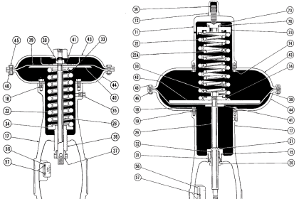
Control Valve Air to Close type :

Control Valve Air to Open type :

Source & Image Credits : By Controls Inc