A relay is an electrically operated switch. Many relays use an electromagnet to mechanically operate a switch, but other operating principles are also used, such as solid-state relays.
Relays are used where it is necessary to control a circuit by a separate low-power signal, or where several circuits must be controlled by one signal.
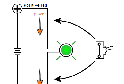
Relay Animation
A simple electromagnetic relay consists of a coil of wire wrapped around a soft iron core, an iron yoke which provides a low reluctance path for magnetic flux, a movable iron armature, and one or more sets of contacts (there are two contacts in the relay pictured).
The armature is hinged to the yoke and mechanically linked to one or more sets of moving contacts. It is held in place by a spring so that when the relay is de-energized there is an air gap in the magnetic circuit. In this condition, one of the two sets of contacts in the relay pictured is closed, and the other set is open. Other relays may have more or fewer sets of contacts depending on their function.
The relay in the picture also has a wire connecting the armature to the yoke. This ensures continuity of the circuit between the moving contacts on the armature, and the circuit track on the printed circuit board (PCB) via the yoke, which is soldered to the PCB.
Relay Parts
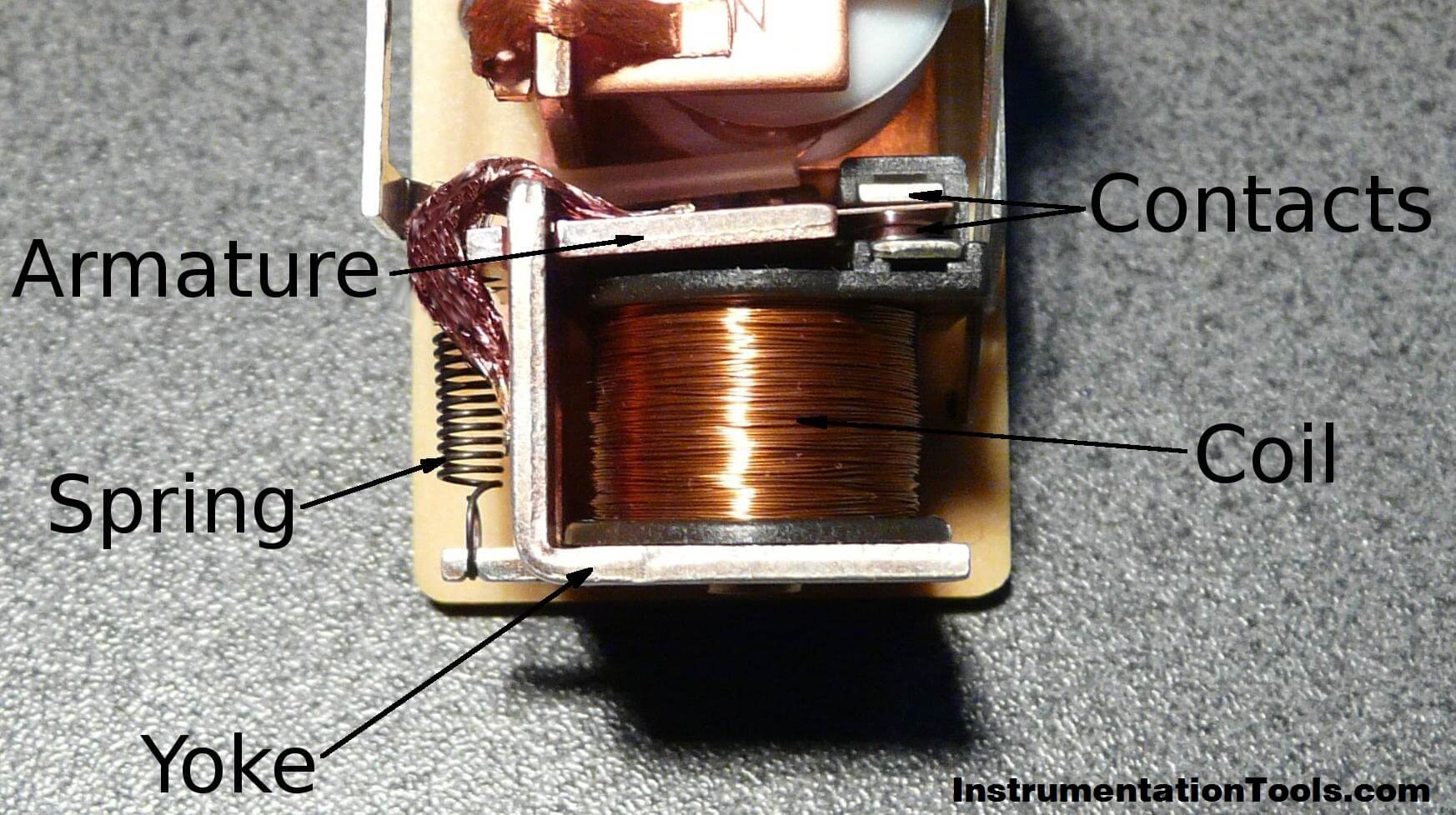
When an electric current is passed through the coil it generates a magnetic field that activates the armature, and the consequent movement of the movable contact(s) either makes or breaks (depending upon construction) a connection with a fixed contact. If the set of contacts was closed when the relay was de-energized, then the movement opens the contacts and breaks the connection, and vice versa if the contacts were open.
When the current to the coil is switched off, the armature is returned by a force, approximately half as strong as the magnetic force, to its relaxed position. Usually this force is provided by a spring, but gravity is also used commonly in industrial motor starters. Most relays are manufactured to operate quickly. In a low-voltage application this reduces noise; in a high voltage or current application it reduces arcing.
When the coil is energized with direct current, a diode is often placed across the coil to dissipate the energy from the collapsing magnetic field at deactivation, which would otherwise generate a voltage spike dangerous to semiconductor circuit components.
Such diodes were not widely used before the application of transistors as relay drivers, but soon became ubiquitous as early germanium transistors were easily destroyed by this surge. Some automotive relays include a diode inside the relay case.
If the relay is driving a large, or especially a reactive load, there may be a similar problem of surge currents around the relay output contacts. In this case a snubber circuit (a capacitor and resistor in series) across the contacts may absorb the surge. Suitably rated capacitors and the associated resistor are sold as a single packaged component for this commonplace use.
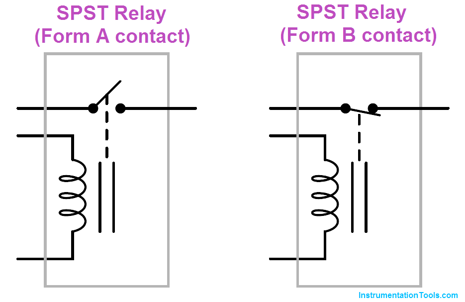
An electromechanical relay is an electrical switch actuated by an electromagnet coil. As switching devices, they exhibit simple “on” and “off” behavior with no intermediate states. The electronic schematic symbol for a simple single-pole, single-throw (SPST) relay is shown here:
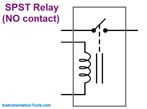
A coil of wire wrapped around a laminated ferrous core provides the magnetic field necessary to actuate the switch mechanism. This electromagnet coil’s actuating influence on the relay’s contact(s) is represented by the dashed line.
This particular relay is equipped with normally open (NO) switch contacts, which means the switch will be in the open (off) state when the relay coil is de-energized. The “normal” status of a switch is the resting condition of no stimulation. A relay switch contact will be in its “normal” status when its coil is not energized.
A single-pole, single-throw relay with a normally-closed (NC) switch contact would be represented in an electronic schematic like this:
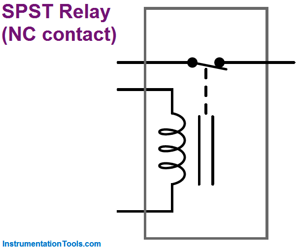
In the electrical control world, the labels “Form-A” and “Form-B” are synonymous with “normally open” and “normally closed” contacts, respectively. Thus, we could have labeled the SPST relay contacts as “Form-A” and “Form-B,” respectively:
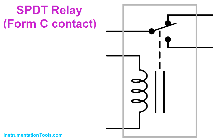
An extension of this theme is the single-pole, double-throw (SPDT) relay contact, otherwise known as a “Form-C” contact.
This design of switch provides both a normally-open and normally closed contact set in one unit, actuated by the electromagnet coil:
A further extension on this theme is the double-pole, double-throw (DPDT) relay contact.
This design of switch provides two sets of Form-C contacts in one unit, simultaneously actuated by the electromagnet coil:
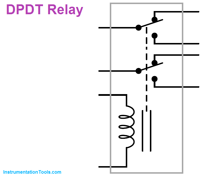
DPDT relays are some of the most common found in industry, due to their versatility. Each Form-C contact set offers a choice of either normally-open or normally-closed contacts, and the two sets (two “poles”) are electrically isolated from each other so they may be used in different circuits.
A common package for industrial relays is the so-called ice cube relay, named for its clear plastic case allowing inspection of the working elements.
These relays plug into multi-pin base sockets for easy removal and replacement in case of failure. A DPDT “ice cube” relay is shown in the following photographs, ready to be plugged into its base (left) and with the plastic cover removed to expose both sets of Form-C contacts (right):
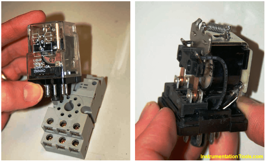
These relays connect to the socket with eight pins: three for each of the two Form-C contact set, plus two more pins for the coil connections. Due to the pin count (8), this style of relay base is often referred to as an octal base.
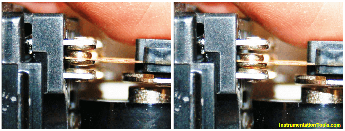
A closer view of one Form-C contact shows how the moving metal “leaf” contacts one of two stationary points, the actual point of contact being made by a silver-coated “button” at the end of the leaf. The following photographs show one Form-C contact in both positions:
Industrial control relays usually have connection diagrams drawn somewhere on the outer shell to indicate which pins connect to which elements inside the relay.
The style of these diagrams may vary somewhat, even between relays of identical function. Take for instance the diagrams shown here, photographed on three different brands of DPDT relay:
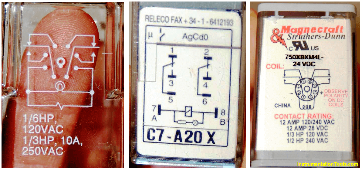
Bear in mind that these three relays are identical in their essential function (DPDT switching), despite differences in physical size and contact ratings (voltage and current capacities).
Only two of the three diagrams shown use the same symbols to represent contacts, and all three use unique symbols to represent the coil.


Sir
I want to download IPhone App.
Hi, I Phone App planning to release soon. Thanks. Keep In Touch.
SIR,
I need a pdf of your documents on instrumentation tools how do i get them
Pdf option will be provided soon. Thanks