Write a PLC program that when a start push button is pressed all the 3 motors are ON and after 3 seconds the first motor shutdowns automatically, then after 7 seconds the second motor shutdowns automatically, and after 12 seconds the last motor shutdowns automatically. At any time if the stop pushbutton is pressed all the three motors are shutdown.
Note the best practice to learn the PLC programming is to start writing the PLC program, take your time before you review the answer.
Inputs and Outputs
I0.0: start push Button (Normally open contact)
I0.1: Stop Push Button (Normally Closed Contact)
Q0.0: Motor 01
Q0.1: Motor 02
Q0.2: Motor 03
T1: Timer 01
T2: Timer 02
T3: Timer 03
Shutdown Motors in Timed Operation
S_PEXT Instruction
S_PEXT (Extended Pulse S5 Timer) starts the specified timer if there is a positive edge at the start (S) input. A signal change is always necessary in order to enable a timer.
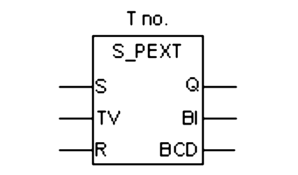
The timer runs for the preset time interval specified at input TV even if the signal state at the S input changes to “0” before the time interval has elapsed. The signal state at output Q is “1” as long as the timer is running.
The timer will be restarted (“re-triggered”) with the preset time value if the signal state at input S changes from “0” to “1” while the timer is running.
The timer is reset if the reset (R) input changes from “0” to “1” while the timer is running. The current time and the time base are set to zero.
PLC Program description
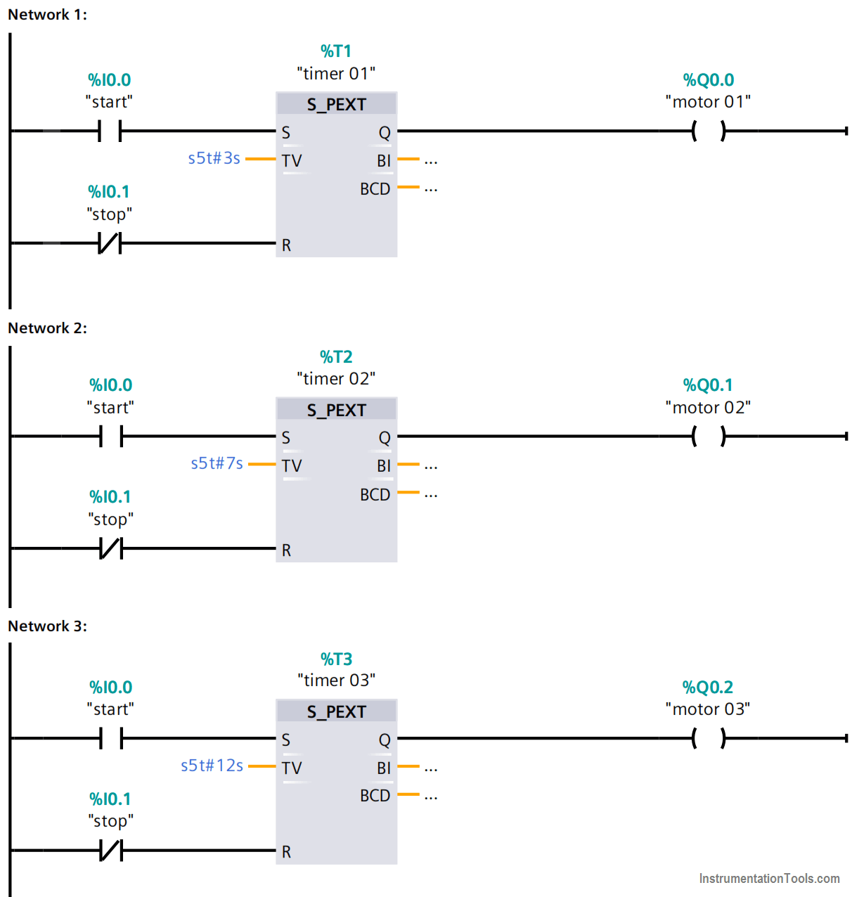
Network 1:
- When the start PB is pressed the “timer 01” is energized and starts to count 3 seconds and runs the “motor 01” for 3 seconds.
- The PEXT is used because the start signal is a pulse as it is a push-button (PB).
- When the stop PB is pressed at any time the timer 01 resets and shutdowns the motor 01.
Note: When we press the Start pushbutton for the first time, then all the motors will be turned ON and runs. In the next networks, I am discussing what will happens for the first time when we press the start push-button.
Network 2:
- When the start PB has pressed the timer 02 is energized and starts to count 7 seconds and runs the “motor 02” for a 7seconds.
- When the stop PB is pressed at any time the “timer 02” resets and shutdowns the motor 02.
Network 3:
- When the start PB is pressed the timer 03 is energized and starts to count 12 seconds and runs the “motor 03” for a 12seconds time.
- When the stop PB is pressed at any time the timer 03 resets and shutdowns the motor 03.
Note: For our simple example, we used motors shutdown time in seconds. In practical industrial applications, it will be in hours, minutes, and seconds depends on our requirements.
Author: Karim Ali Anwar
If you liked this article, then please subscribe to our YouTube Channel for PLC and SCADA video tutorials.
You can also follow us on Facebook and Twitter to receive daily updates.
Read Next:
- Motor Speed Control
- Motor Clockwise Operation
- What is Auto-closing?
- Siemens Memory Cards
- Online & Offline Logics