Whenever anyone is performing Calibration, they should have Raw DataSheet to note down the readings.
Why it is called as Raw DataSheet?
As readings are entered in Raw DataSheet during performing Calibration activity, readings are raw and need to process and analyzed before entering into the calibration certificate. Therefore, It is called a Raw datasheet.
Raw DataSheet for Pressure Calibration
The raw datasheet for Pressure Calibration is prepared according to ISO/IEC 17025:2017 and DKD R-6-1.
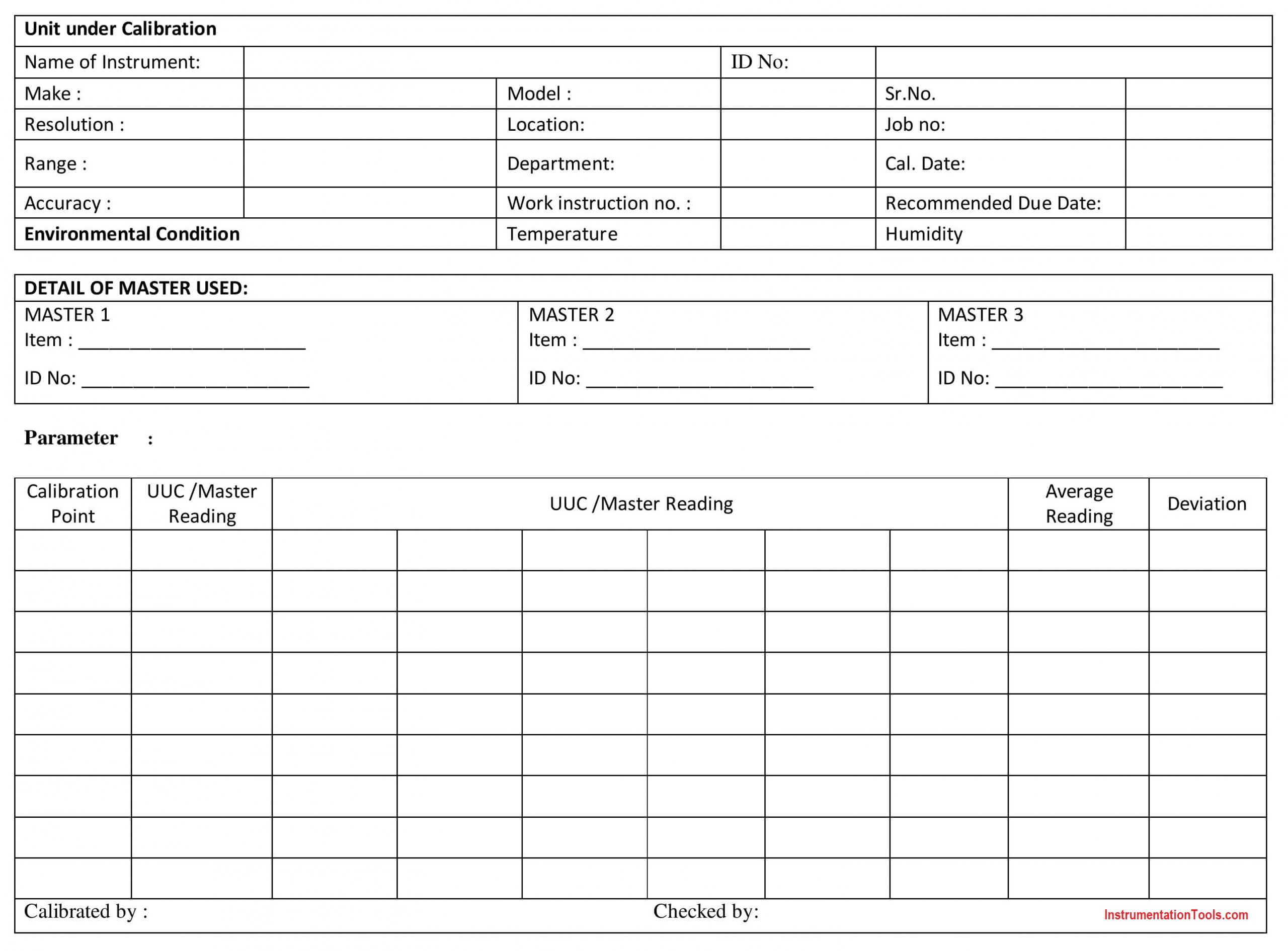
Raw DataSheet for Pressure Calibration of Accuracy 0.6 % or better (Table 1)
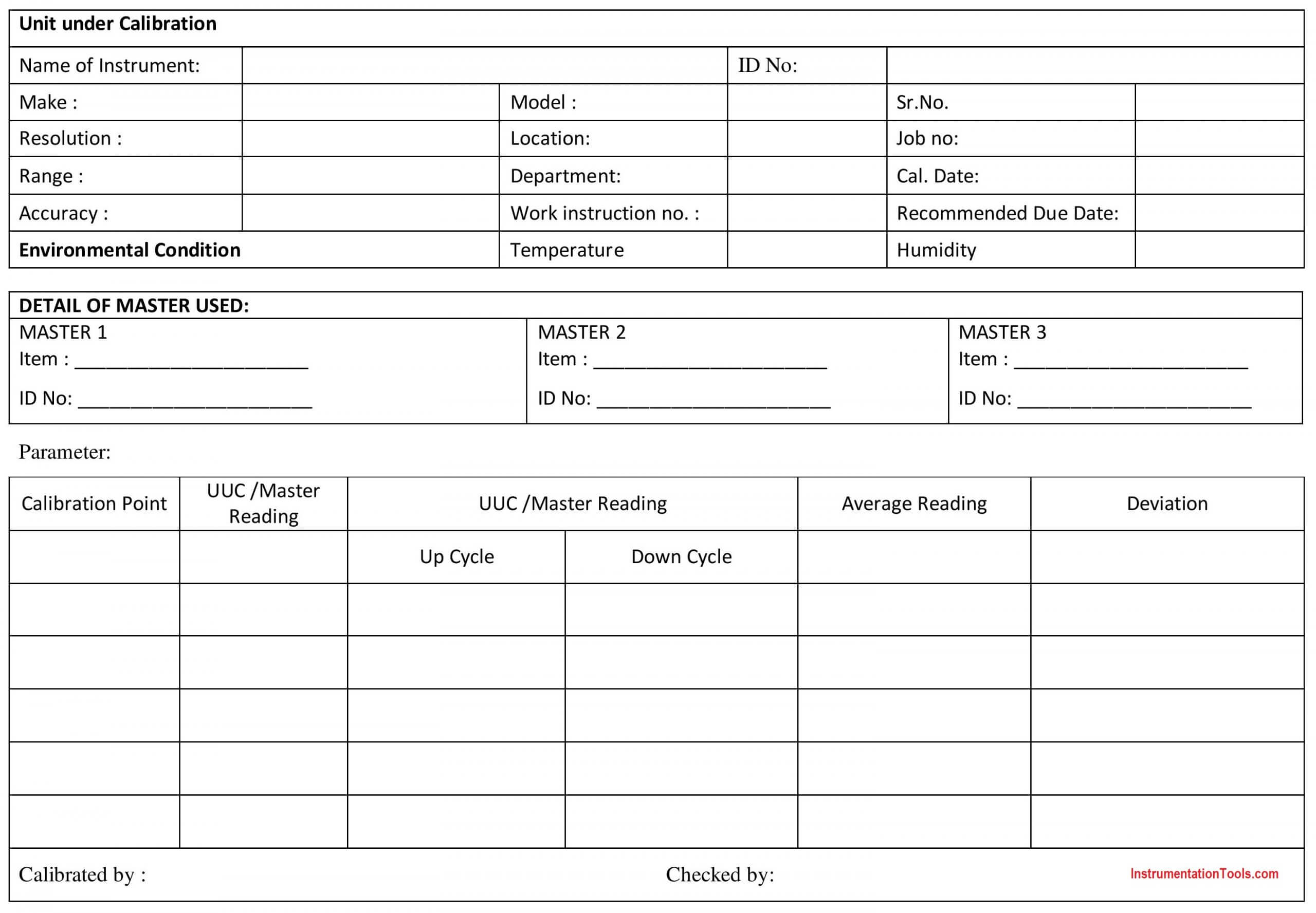
Raw DataSheet for Pressure Calibration of Accuracy greater than 0.6 % (Table 2)
Also Read: Pressure Gauge Calibration according to Standard DKD-R-6-1
Main Parts of Datasheet
Three main parts of the Raw Datasheet are:
- Details of UUC
- Details of Master Equipment used
- Readings
Details of UUC
Note down details of UUC as the name of Instrument (Pressure Gauge/Vacuum Gauge/Compound Gauge), Identification Number, Make, Range, Resolution, Accuracy, Calibration Date, Recommended Due Date, Environmental Conditions
Details of Master Equipment used
Note down Name of Master Equipment and Identification Number
Readings
This is the most important part of the Raw Data Sheet. As Instrument is said to be Okay or Faulty according to readings entered.
The above Raw Datasheet is for pressure Gauge Calibration of accuracy less than 0.6% (Table 1) and accuracy greater than 0.6 % (Table 2)
First Column is of Calibration Point
For Pressure gauge accuracy less than 0.6 %, it is 9 point calibration. Therefore choose 9 points covering the full range including zero. Refer Table 1
For Pressure gauge accuracy of more than 0.6 %, it is 5 point calibration. Therefore choose 5 points covering the full range including zero. Refer Table 2
Second Column is of UUC/Master Reading
If Calibration Point is attained on UUC and corresponding reading is measure on Standard Pressure Gauge. Mark UUC Reading on above Table and note down corresponding UUC reading as Calibration point is attained.
If Calibration Point is attained on Master and corresponding reading is measure on UUC Pressure Gauge. Mark Master Reading on above Table and note down corresponding Master reading as Calibration point is attained.
The third Column is of UUC/Master Reading
If we are noting down UUC readings in this Column, UUC should be marked in the above table
If we are noting down Master readings in this Column, Master should be marked in the above table
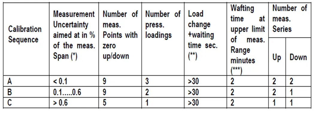
Table 1
For Accuracy < 0.1 %, Two UP Cycle, and Two Down Cycles are performed.
UP—Down—UP—Down
For Accuracy 0.1% to 0.6 %, Two UP cycles and One Down Cycle are performed.
UP—Down—UP
For better results, the Three UP Cycle and Three Down Cycle are performed.
UP—Down—UP—DOWN—UP—DOWN
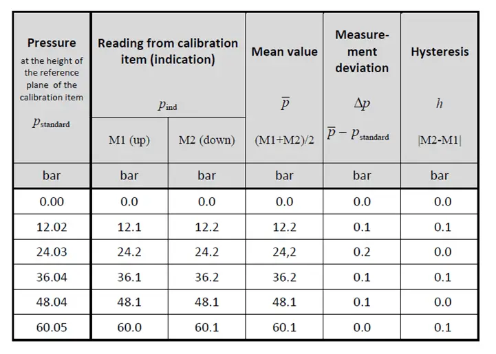
Table 2
For Accuracy >0.6 %, One UP Cycle and One Down Cycle are performed.
UP—Down
UP Cycle Readings are from Zero readings to Maximum Range
Down Cycle Readings are from Maximum Range to Zero reading
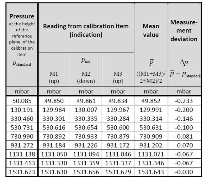
Fourth Column is of Average Reading
Average readings are Calculated as Average of Average reading of Up-Cycle and Average reading of Down Cycle
M1, M3, M5 are Up Cycles
M2, M4, M6 are Down Cycles.
For Three Up and Three down Cycles average is calculated as
[{(M1+M3+M5)/3} + {(M2+M4+M6)/3}] / 2
For Two Up and Two down Cycles average is calculated as
[{(M1+M3)/2} + {(M2+M4)/ 2}] / 2
For Two Up and One down Cycles average is calculated as
[{(M1+M3)/2} + M2] / 2
For One Up and One down Cycles average is calculated as
(M1+M2)/ 2
Fifth Column is of Deviation
The deviation is the difference between Standard reading and UUC reading
Calculated as Standard Reading – UUC Reading (or) UUC Reading – Standard Reading.
Deviation or difference can be calculated either way
Ref- DKD-R-6-1
Sample Datasheets
Sample Readings Raw DataSheet for Two-Up and One Down Cycle
Sample Readings Raw DataSheet for One Up and One Down Cycle
If you liked this article, then please subscribe to our YouTube Channel for Instrumentation, Electrical, PLC, and SCADA video tutorials.
You can also follow us on Facebook and Twitter to receive daily updates.
Read Next:
- Prover Tank Calibration
- History of Measurement
- Temperature Sensor Calibration
- Compare Accuracy and Precision
- Control Valve Stroke Test Procedure


Thanks so for this educative presentation on pressure calibration.This is really helpful. It has broadened my knowledge of pressure calibration.
But can you I have a (Sample Readings Raw DataSheet for Two-Up and Two-Down cycle?
Thanks so for this educative presentation on pressure calibration.This is really helpful. It has broadened my knowledge of pressure calibration.
Please, can I have a (Sample Readings Raw DataSheet for Two-Up and Two-Down cycle?