Pressure Gauges : Remote and Chemical Seals
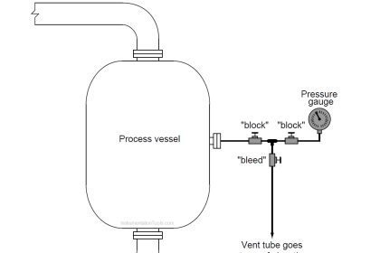
Isolating diaphragms have merit even in scenarios where pressure pulsations are not a problem. Consider the case of a food-processing system where we must remotely measure pressure inside a mixing vessel:
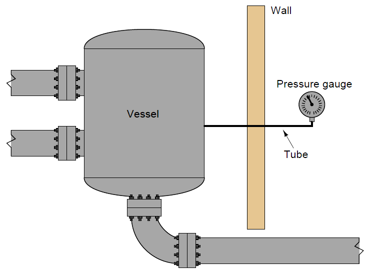
The presence of the tube connecting the vessel to the pressure gauge poses a hygiene problem. Stagnant process fluid (in this case, some liquid food product) inside the tube will encourage microbial growth, which will eventually contaminate the vessel no matter how well or how often the vessel is cleaned. Even automated Clean-In-Place and Steam-In-Place (CIP and SIP, respectively) protocols where the vessel is chemically purged between batches cannot prevent this problem because the cleaning agents never purge the entire length of the tubing (ultimately, to the bourdon tube or other sensing element inside the gauge).
A solution to this problem is to install an isolating diaphragm at the vessel, and a liquid-filled capillary tube to transfer sensed pressure to the instrument. Process pressure presses against this diaphragm, which in turn transfers pressure to the “fill fluid” inside the capillary tube. This sealed fill fluid then presses against the instrument’s sensing element (diaphragm, bourdon tube, bellows, etc.). Process (food) liquid cannot enter this sealed tube, and the isolating diaphragm will be cleaned with every CIP cycle. Thus, we completely eliminate the problem of microbial contamination:
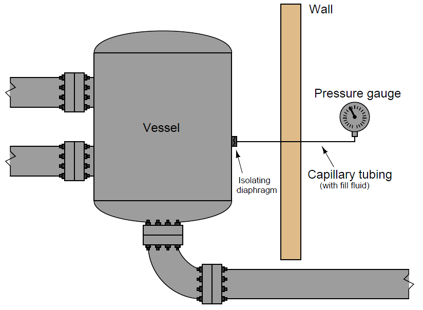
Such systems are often referred to as remote seals, and they are available on a number of different pressure instruments including gauges, transmitters, and switches. If the purpose of an isolating diaphragm and fill fluid is to protect the sensitive instrument from corrosive or otherwise harsh chemicals, it is often referred to as a chemical seal.
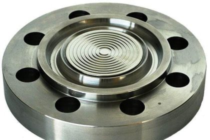
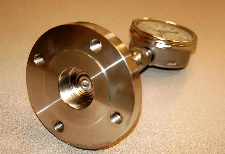
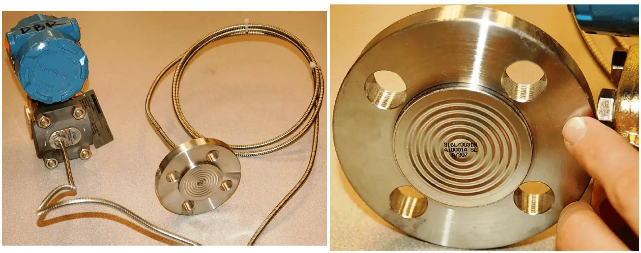
The following photograph shows a pressure gauge equipped with a chemical seal diaphragm. Note that the chemical seal on this particular gauge is close-coupled to the gauge, since the only goal here is protection of the gauge from harsh process fluids, not the ability to remotely mount the gauge:
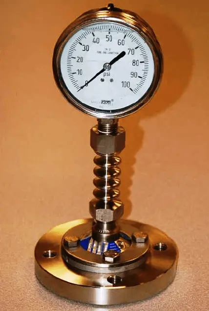
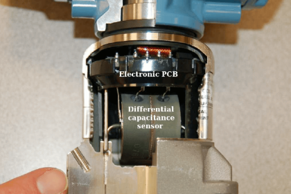
A view facing the bottom of the flange reveals the thin metal isolating diaphragm keeping process fluid from entering the gauge mechanism. Only inert fill fluid occupies the space between this diaphragm and the gauge’s bourdon tube:
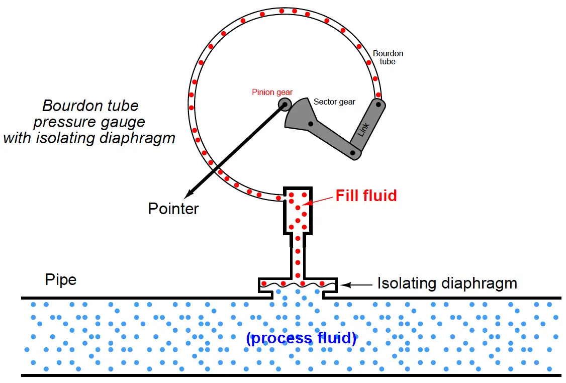
The following illustration shows how the fill fluid transfers process fluid pressure to the gauge’s bourdon tube element while isolating that bourdon tube from the process fluid (shown here inside a pipe):
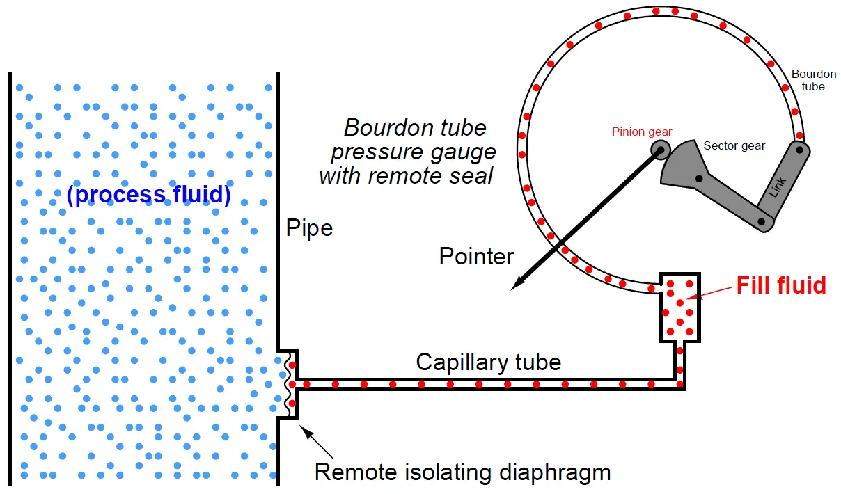
The only difference between this chemical-seal gauge and a remote-seal gauge is the small diameter capillary tubing used to connect the gauge to a remote diaphragm. An illustration showing the internals of a remote seal system appears here:
Direct-reading gauges are not the only type of pressure instruments benefiting from remote seals. Pressure switches and pressure transmitters may also employ remote seals for the same reasons: protection of the transmitter sensor from harsh process fluid, elimination of impulse tube clogging problems, and/or the prevention of “dead-end” tube lengths where organic process fluid would stagnate and harbor microbial growths. In this photograph, you see three pressure sensing devices (gauge, transmitter, and switch, from top to bottom), each one with its own remote seal to sense fluid pressure in a large pipe:
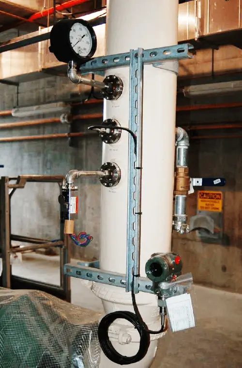
The pressure transmitter (a Yokogawa unit) is the only instrument shown here using a capillary tube. The other two instruments use short lengths of rigid pipe. The capillary is visible in this photograph as a coiled tube covered in black plastic. It is actually a very small-diameter metal tube enclosed in a spiral-metal protective sheath which is in turn covered by black plastic.
This particular application happens to be in wastewater treatment, where sludge has a tendency to clog instrument impulse lines connected to the main piping. With remote seals in place, that problem is completely eliminated.
The following photograph shows a Rosemount model 1151 electronic pressure transmitter equipped with a remote sealing diaphragm. Here we may see the coiled metal (“armor”) sheath protecting the capillary tube from damage ( Below Figure – Left):
A close-up view of the sealing diaphragm shows its corrugated design, allowing the metal to easily flex and transfer pressure to the fill fluid within the capillary tubing ( Above Figure – Right)
As with the isolating diaphragms of the pressure-sensing capsule, these remote diaphragms need only transfer process fluid pressure to the fill fluid and (ultimately) to the taut sensing element inside the instrument. Therefore, these diaphragms perform their function best if they are designed to easily flex. This allows the sensing diaphragm to provide the vast majority of the opposing force to the fluid pressure, as though it were the only spring element in the fluid system.
The connection point between the capillary tube and the transmitter’s sensor capsule is labeled with a warning never to disassemble, since doing so would allow air to enter the filled system (or fill fluid to escape from the system) and thereby ruin its accuracy:
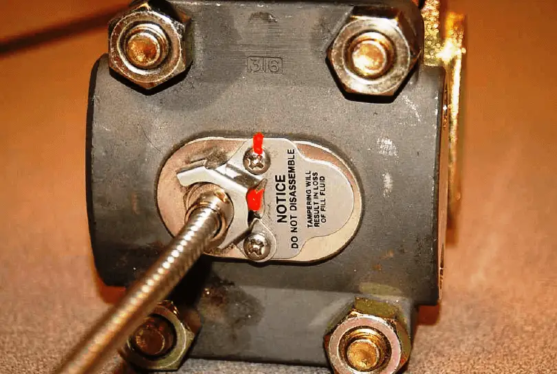
In order for a remote seal system to work, the hydraulic “connection” between the sealing diaphragm and the pressure-sensing element must be completely gas-free so there will be a “solid” transfer of motion from one end to the other. The presence of gas bubbles in the filled system will cause some of the isolating diaphragms’ motion to be “lost” rather than be fully transferred to the instrument’s pressure-sensing element. For this reason, the capillary system must remain perfectly sealed at all times! Breaching this seal, even for just a brief moment, will ruin the system.
A protective measure visible in this photograph is the orange compound painted on the screw head and on the capillary tube connector. This is simply a visual indication that the factory seal is still intact, since any motion of the screw or of the tube connector would crack the brittle orange compound and betray the breach.
A potential problem with using remote diaphragms is the hydrostatic pressure generated by the fill fluid if the pressure instrument is located far away (vertically) from the process connection point. For example, a pressure gauge located far below the vessel it connects to will register a greater pressure than what is actually inside the vessel, because the vessel’s pressure adds to the hydrostatic pressure caused by the liquid in the tubing:
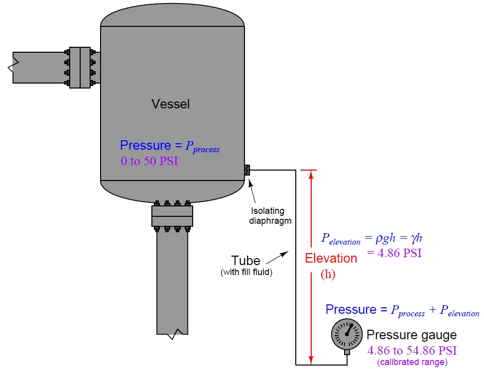
This pressure may be calculated by the formula P = ρgh or P = γh where ρ is the mass density of the fill liquid or γ is the weight density of the fill liquid. For example, a 12 foot capillary tube height filled with a fill liquid having a weight density of 58.3 lb/ft3 will generate an elevation pressure of almost 700 lb/ft2, or 4.86 PSI. If the pressure instrument is located below the process connection point, this 4.86 PSI offset must be incorporated into the instrument’s calibration range. If we desire this pressure instrument to accurately measure a process pressure range of 0 to 50 PSI, we would have to calibrate it for an actual range of 4.86 to 54.86 PSI.
The reverse problem exists where the pressure instrument is located higher than the process connection: here the instrument will register a lower pressure than what is actually inside the vessel, offset by the amount predicted by the hydrostatic pressure formulae ρgh or γh.
In all fairness, this problem is not limited to remote seal systems – even non-isolated systems where the tubing is filled with process liquid will exhibit this offset error. However, in filled-capillary systems a vertical offset is guaranteed to produce a pressure offset because fill fluids are always liquid, and liquids generate pressure in direct proportion to the vertical height of the liquid column and its density. Many common remote seal fill fluids have specific gravity ratings greater than 1 (i.e. they are denser than water) which means the offset error resulting from hydrostatic pressure will be even greater than that of a water-filled tube.
A similar problem unique to isolated-fill pressure instruments is measurement error caused by temperature extremes. Suppose the liquid-filled capillary tube of a remote seal pressure instrument is placed too near a hot steam pipe, furnace, or some other source of high temperature. The expansion of the fill fluid may cause the isolation diaphragm to extend to the point where it begins to tense and add a pressure to the fill fluid above and beyond that of the process fluid. Cold temperatures may wreak havoc with filled capillary tubes as well, if the fill fluid congeals or even freezes such that it no longer flows as it should. Fill fluid expansion/contraction effects may be mitigated by keeping the volume of the fill fluid to a minimum, which is why capillary (small-diameter) tubes are used to connect remote seals with instruments.
Another problem with remote seal pressure instruments is a time delay caused by the viscosity of the fill fluid as it moves through the small-diameter capillary tubes. This makes the pressure instrument slow to respond to changes in process fluid pressure, as though the pressure instrument were equipped with an (undesired) pressure snubber. While minimal capillary tube diameter reduces the effects of temperature changes, it increases the effect of time delay.
Proper mounting of the instrument and proper selection of the fill fluid will help to avoid such problems. All in all, the potential for trouble with remote- and chemical-seal pressure instruments is greatly offset by their benefits in the right applications.
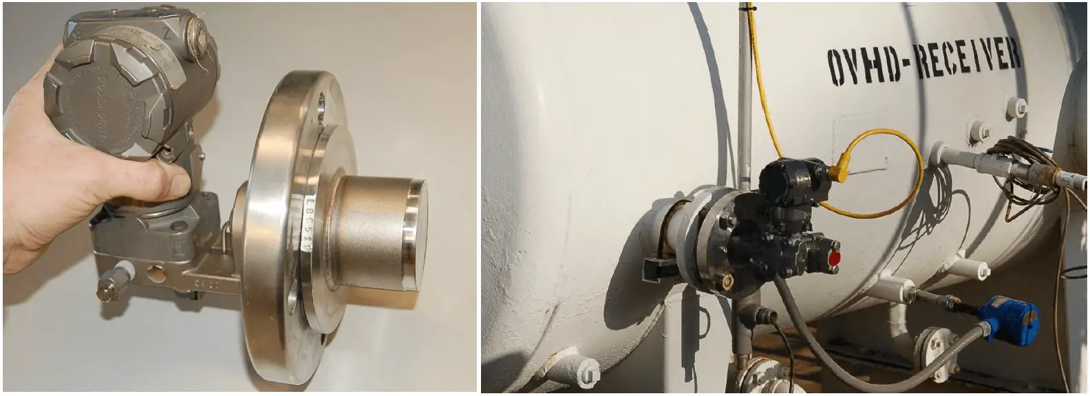
Some diaphragm-sealed pressure transmitters are equipped with close-coupled seals rather than remote seals to minimize hydrostatic, temperature, and time delay effects caused by fill fluid inside a capillary tube. A Rosemount extended-diaphragm pressure transmitter appears in the left-hand photograph, while a Yokogawa transmitter of the same basic design is shown installed in a working process in the right-hand photograph:
Credits : Tony R. Kuphaldt – Creative Commons Attribution 4.0 License