A Pyrometer is any non-contacting device that intercepts and measures thermal radiation. This measure is used to determine temperature, often of the object’s surface.
The word pyrometer comes from the Greek word for fire, “πυρ”, and meter, meaning to measure. Pyrometer was originally coined to denote a device capable of measuring temperatures of objects above incandescence (i.e. objects bright to the human eye).
Pyrometers are used to ‘read’ radiated heat in steel industries, ceramic manufacturing and other applications requiring high temperature from a few hundreds to thousands of degrees Celsius of temperature. Most pyrometers come in a set of a sensor and a controller. The controller may come readouts of analog or digital.
I have here some pictures while in the process of calibrating pyrometers using a black body.
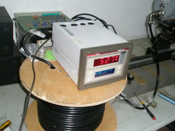
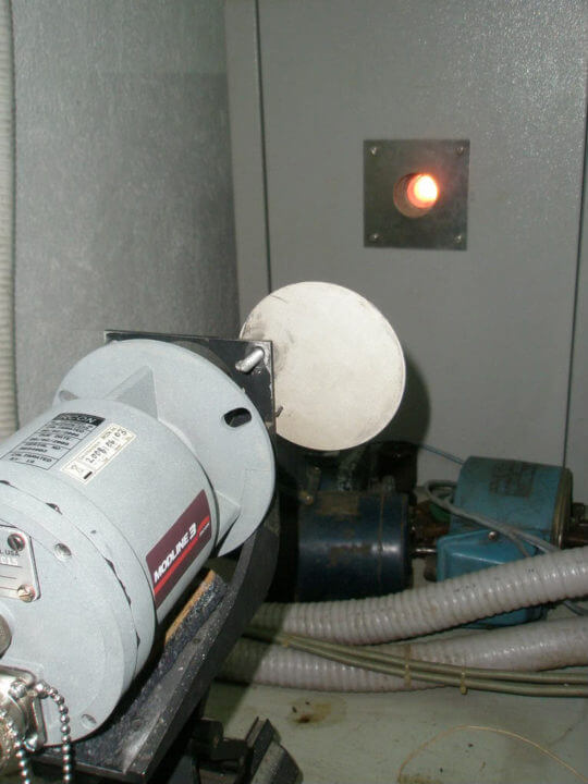
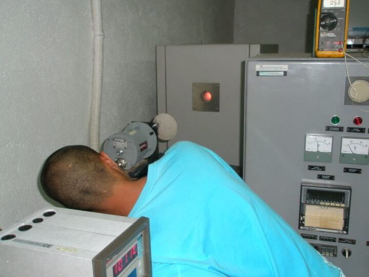

Below is a note on the blackbody furnace and proposed standard procedure in the calibration of “Infrared Thermometer” otherwise known as “Pyrometers” used in rolling mills.
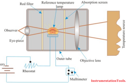
Every object radiates thermal energy at temperatures above absolute zero. Measuring the temperature of an object using optical pyrometer is based on the principle that the thermal radiation from the object being measured is a function of its temperature. For any particular temperature and wavelength, the energy radiated by a surface is directly proportional to the spectral emissivity of the object. Emissivity is the value associated with the surface’s ability to get of heat by radiating thermal energy, and different substances have different emissivities. The value of a substance’s spectral emissivity is a number in the range from 0 to 1.0, which is the ratio of the energy radiated by object’s surface to the energy radiated by a perfect blackbody at the same temperature.
The primary issue when using infrared thermometer sensors is that a real object does not behave like a perfect radiator.
Having calibrated an infrared thermometer on a perfect radiator (blackbody source), the ability to measure temperature of a real object relates directly to how well the object’s emissivity is known. An object with an emissivity of 0.8 emits only 80 percent of the energy of the blackbody, so unless one accounts for an object’s actual emissivity, the indicated temperature reading will be lower than the object’s actual temperature. Most radiation thermometers provide for emissivity adjustment.
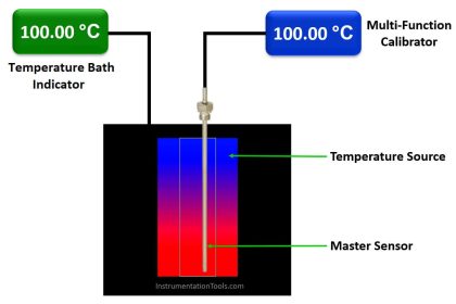
The instrument manufacturer calibrates an infrared thermometer (pyrometer) by aiming it a blackbody source, which is designed specifically for testing and calibrating infrared thermometers. Blackbody sources resemble a furnace with an opening to view a surface or cavity heated and controlled to a selected temperature.
There are basically two types of infrared calibration sources, the Hot Plate Blackbody and the Cavity Type Blackbody source. But, let us concentrate on the cavity type blackbody source as this is available within the author’s reach.
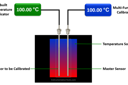
The cavity type blackbody source consists of a blind hole in a cylinder or sphere where the temperature of teh cavity is controlled by a temperature controller, using a thermocouple probe. The cavity type blackbody source has a higher emissivity compared to a hot plate blackbody source. The emissivity of a cavity type blackbody source is typically 0.98 or higher which makes them ideal for precise calibration tasks.
When using a blackbody calibration source, we need to follow certain ground rules:
- The infrared thermometer should be aimed perpendicular to the target area of the blackbody unit. If aimed at an angle, reflected infrared radiation energy can impair calibration accuracy.
- The field of view area of the thermometer at a selected distance should be smaller than the target area of the blackbody unit.
- Do not bring the infrared thermometer too close to the target area of the blackbody especially at high temperatures. The radiated heat from the blackbody can not only impair the calibration accuracy but also can potentially damage the unit under test.
- Always aim the infrared thermometer to the center of the target area.
- When changing the temperature setpoint on the blackbody unit, make sure the unit is fully stabilized to the new temperature setting before making any calibration test. Usually going up in temperature takes less time than going down in temperature.
- Do not unplug a blackbody calibration source while it hot. There are usually built-in fans to remove the heat even when the power switch is off. Let the internal fan continue to run until the unit is cooled down.
User should be guided on recommended operating conditions. These factors, along with proper maintenance, will allow safe and satisfactory operation of the furnace.
Safety is very important when working with furnaces. Follow safety procedures for working around the furnace. Controllers are used to control temperatures to constant value ( the operators sets the required temperature; when achieved the temperature is maintained on this value until next intervention of the operator) or to control temperature according to simple program (the operator sets the temperature build-up speed).
Step 1.
• Set-up and mount the pyrometer’s sensor and controller. When blackbody furnace has been properly prepared and ready for operation. Operating suggestions: Manual intervention if batch calibration for auto mode, refer to controller operating manual ramp programming.
Step 2.
• Power up the blackbody furnace to heat up 400 degrees Celsius at rate of 3 degrees Celsius per minute. Hold at 400 degrees Celsius for two hours or more (preferably overnight). Let furnace to heat up until set point 400 degrees Celsius is stabilized at this set point.
Step 3.
• While the furnace is building up its temperature, do preliminary observation on the controller before turning on the power, check if the indicator/processor analog meter pointer is in zero position. If not, with a small screwdriver, gently turn the advancement screw as necessary to zero the pointer at the left side of the scale.
Step 4.
• Operator should follow a projected heating curve for the duration of heating at the desired temperature for calibration. Let furnace heat up until each REF. # set point and stabilized at this set point.Step
• Size = Pre-determined value for temperature change.
• Ramp = Select the pre-determined rate changes to the next value.
• Increment using numerical keypad (increment and decrement).
Step 5.
• Power on the controller, and allow 20 minutes warm-up time.
Step 6.
• Cover the objective lens with a solid, opaque object that will completely block any external radiation.
Step 7.
• The Response Time control must be in the FAST position. If a Peak Picker option is installed, toggle the Peak Picker switch to DIRECT.
Step 8.
• Depress the momentary toggle switch label CALIBRATE.
• If your instrument has and analog meter, observe if the meter reads within the read CAL. ZONE. If the meter reads outside the CAL. ZONE, make some adjustment.
• If your instrument has a digital readout, depressing the Calibrate switch should produce a reading of 500 +/- 10 digits, regardless of model. If it does not, do some calibration.
• Normal calibration level: Pointer to center of CAL position on analog display; numerical reading of 500 +/- 10 digits on digital display.
Note: Refer to manufacturer’s infrared thermometer manual for Calibration Check.
Step 9.
• Without any calibration adjustment to be undertaken, take reading on the projected temperatures for upscale and then downscale reading. This is to determine possible error. Set the Emissivity/E-slope adjustment to the highest value of the controller.
Step 10.
• If calibration is to be done for several pyrometer set or batch, repeat steps3 to 9 and note the reading taken for each set of upscale and downscale reading.
Step 11.
• With each set of the reading taken for upscale and the downscale, determine if there are noticeable errors. If reading is linear and within the projected temperature range. No further adjustment is needed, the pyrometer set is calibrated.
Step 12.
• If error is present, calibrate the pyrometer set. By setting the blackbody furnace temperature to the lowest range of the controller then calibrate the controller to zero.
Step 13.
• Do step 12 to other pyrometer set with determined error.
Step 14.
• Increase the blackbody furnace temperature setting to the highest range of the controller then calibrate the controller for this setting.
Step 15.
• Do step 14 to other pyrometer set with determined error.
Step 16.
• Check upscale reading against projected temperature of the pyrometer then set and take note of its reading. If this batch calibration, do the same to the other pyrometer sets.
Step 17.
• Check the downscale reading against the projected temperature of the pyrometer set and take note of its reading. If this is a batch calibration do the same to other pyrometer sets.
Steps 18.
• If there are still discrepancies on the linearity, repeat step 12 to 17. If there are none, calibration is done.
Step 19.
• Cool down blackbody slowly. (Refer to the cooling curve below).
Note: During operation, one of the most important requirements for accurate temperature measurements is the Emissivity/E-slope adjustment to effectively tune circuits measurement to the characteristics of the process material. To get a true measure of temperature, we must set the Emissivity/E-slope control in the system to match Emissivity of the material being measured.
Also Read: Temperature Measurement Interview Questions


if the aperture of the blackbody is not meet the size of the parallel beam of the instrument,what should we do?