In this article, we will learn about the Robot anatomy and configuration, Robot’s reference frame, programming methods, and characteristics.
Robot Anatomy
The anatomy of the robot is concerned with the physical construction of the body, arm, and wrist of the machine.
Nowadays, most robots used in industries are mounted on a base that is fastened to the floor. The whole body of the robot was attached to the base and the arm assembly is attached to the body. At the end of the arm is the wrist.
The wrist consists of a number of components that allow it to be oriented in a variety of positions. The movement between various components of the body, arm, and wrist is provided by a series of joints.
These joints may be in either rotating or sliding motions. The body, arm, and wrist assembly combinedly are known as manipulators.
The tool or hand attached to the robot’s wrist is known as the end effector.
Robot Configuration
Industrial robots are available in a wide variety of sizes, shapes, and physical configurations. These configurations are mainly depending on the movement of joints.
Those joints are known as Prismatic joints or Linear joints denoted by P, revolute joints denoted by R, and spherical joints denoted by S.
The vast majority of today’s commercially available robots possess one of five basic configurations.
They are
- Cartesian configuration
- Cylindrical configuration
- Polar or Spherical configuration
- Jointed-arm configuration
- SCARA configuration
Cartesian Robot Configuration (3P)
These robots are made of three linear joints that position the end effector, which is usually followed by additional revolute joints that orientate the end effector. 3P represents three Prismatic or Linear joints used in the robots.
By moving the three slides relative to one another, the robot is capable of operating within a rectangular work envelope.
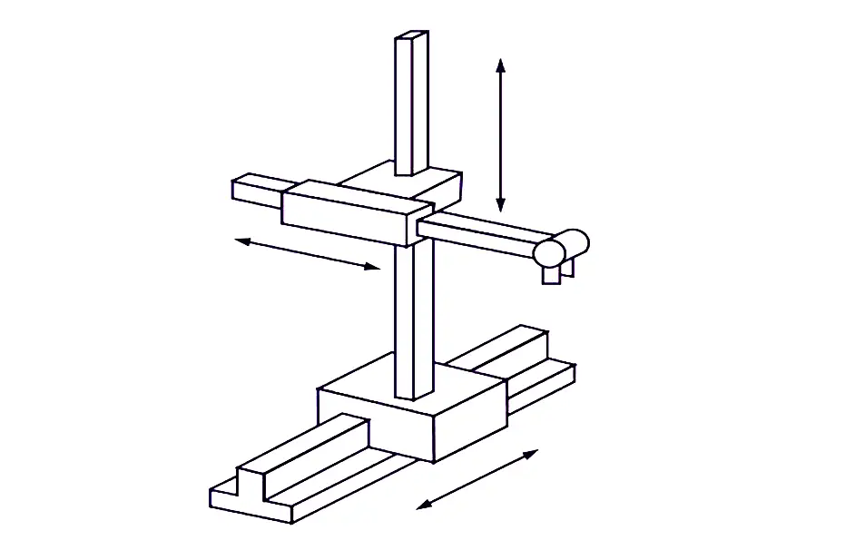
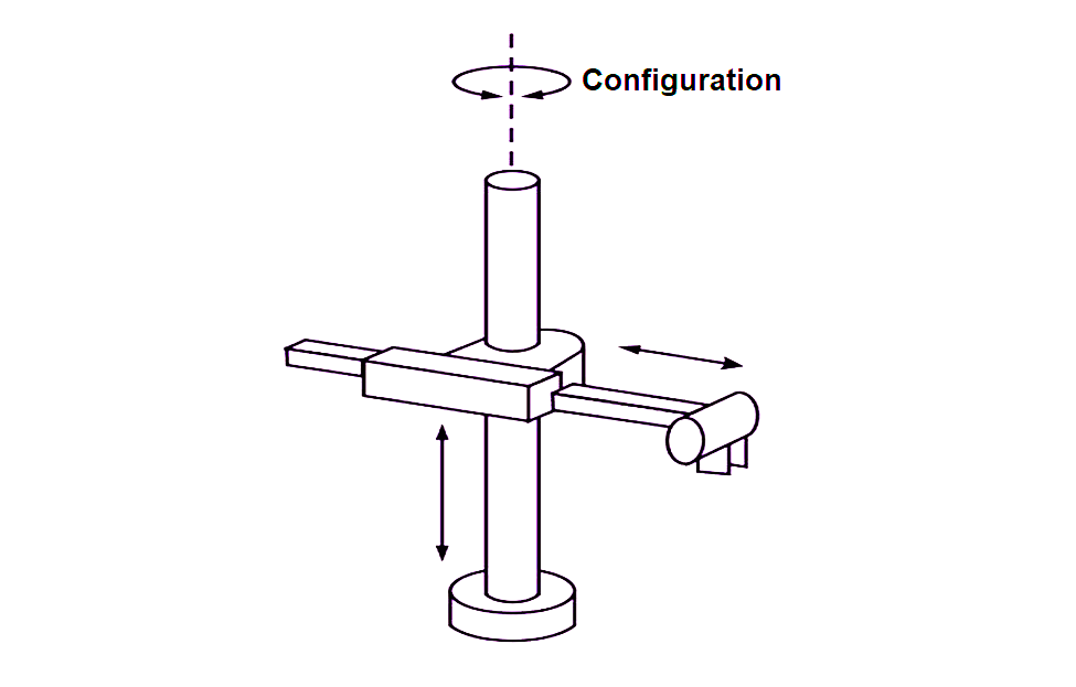
Cylindrical Robot Configuration (PRP)
The cylindrical configuration uses a vertical column and a slide that can be moved up or down along the column. The robot arm is attached to the slide so that it can be moved radially with respect to the column.
By rotating the column, the robot is capable of achieving a workspace that approximates a cylinder. This cylindrical configuration has two Prismatic or Linear joints and one revolute joint, (PRP) denotes this only.
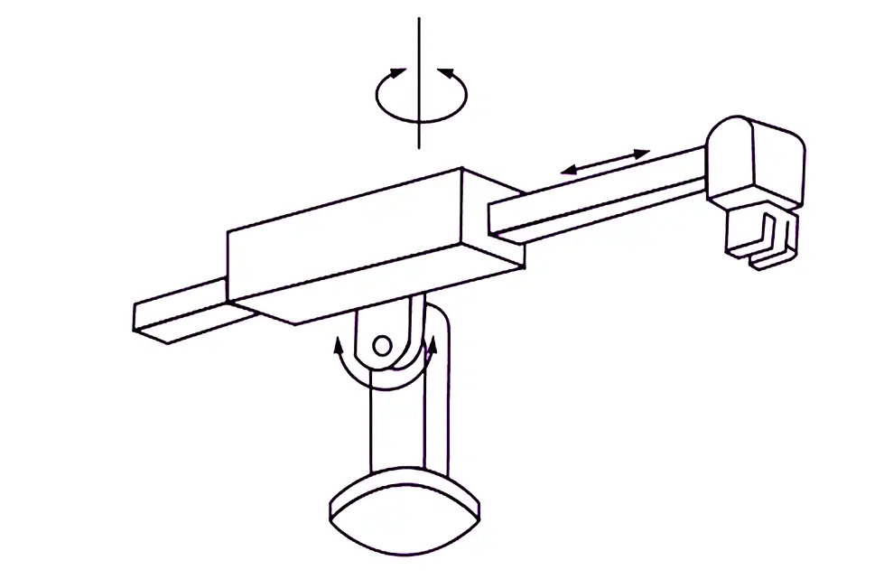
Polar or Spherical Robot Configuration (P2R)
The polar configuration uses a telescopic arm that can be moved up or down about a horizontal pivot. The pivot is mounted on a rotating base.
These joints provide the robot with the capability to move its arm within a spherical space and hence the name spherical coordinate robot is sometimes applied to this space.
This system has one Prismatic and two Revolute joints that denote the P2R.
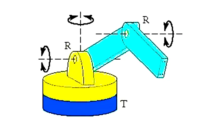
Jointed Arm Robot Configuration (3R)
The jointed Arm configuration is made up of rotating joints. This robot configuration is also sometimes called anthropomorphic as its anatomy is similar to the Human arm.
These configuration joints are all revolute (3R). They are the most common configuration for industrial robots.
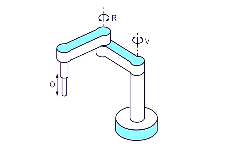
SCARA Configuration
SCARA stands for Selective Compliance Assembly Robot Arm. SCARA robots have two or three revolute joints that are parallel and allow the robot to move in a horizontal plane, plus a linear joint that moves vertically.
SCARA robots are very common in assembly operations.
Robot Reference Frame
Robots may be moved relative to different coordinate frames. In each type of coordinate frame, the motions will be different.
Robot motions are accomplished in the following three coordinate frames.
They are:
- World Reference Frame
- Joint Reference Frame
- Tool Reference Frame
World Reference Frame
This is a universal coordinate frame, as defined by the x, y, and z axes. In this type, the joints of the robot move simultaneously in a coordinated manner to create motions along the three major axes.
The world reference frame is used to define the motions of the robot relative to the other objects, define other parts and machines with which the robot communicates and define motion trajectories.
Joint Reference Frame
The joint reference frame is used to specify the movements of individual joints of the robot. In this case, each joint is accessed and moved individually so one joint will be moved at a time.
Depending on the prismatic, revolute, and spherical joints used the motion of the robot hand will be different.
Tool Reference Frame
Tool frame specifies movements of the robot hand relative to a frame attached to the hand. All motions are relative to this local frame denoted by n,o,a axes.
This frame will move with a robot as the robot changes its position similarly this frame reference will change. The resulting motions relative to it are also different depending on where the arm is and the direction of the tool frame.
The joints of the robot must move simultaneously to create coordinated motions about the tool frame.
Robot Programming Modes
All the robots need to program for doing definite operations. Robots may be programmed in a number of different modes, depending on the robot and how sophisticated it is.
The Following modes are common:
Physical Setup
In this mode, the operator sets up switches and hard stops that control the motions of the robot. This mode is usually used along with other devices such as PLC.
Lead through or Teach Mode
In this Teach mode robot, joints are moved with the help of a teach pendant – it is like a joystick. The desired location and orientation are achieved, and that location is taught to the controller.
During Playback, the controller moves the joints to the same locations and orientation. This mode is usually a point-to-point control, only the points which are taught are guaranteed to reach.
Continuous Walk-Through Mode
In this mode, all robot joints are moved simultaneously, while the motion is continuously sampled and recorded by the controller.
During playback, the exact motion that was recorded is executed. The motions are taught by the operator, either through a model or by physically moving the end-effector.
Software Mode
In this mode the motions of the robots were controlled by programming through software, it may be online or offline.
Nowadays, this software mode is used in all industries because of its sophistication and versatility. Through this mode, we can get sensory information, conditional statements, and branching.
The main advantage of the software mode is we can simulate it virtually in the software itself before deploying it into the robot model. In the simulation itself, we can find all the necessary information about robot movements and functions.
Robot Characteristics
Every robot has some characteristics for working, depending on the function these characteristics may vary. But some characteristics are common in all types of robots.
The following are some common characteristics of robots.
Payload
Payload is the weight a robot can carry and still remains within its other specifications. In other words, Payload is the amount of weight a robot can carry or lift to do the work without losing its accuracy and efficiency in work.
The robot can lift the weight above its Payload but it does not give the accuracy as expected.
Reach
Reach is the maximum distance a robot can reach within its work envelope. Reach is a function of the robot’s joints and lengths and its configuration.
This is an important specification for industrial robots and must be considered before a robot is selected and installed.
Precision
Precision is defined as how accurately a specified point can be reached. This is s function of the resolution of the actuators as well as the robot’s feedback device.
Most industrial robots have precision in the range of 0.001 inches or better. The precision is a function of how many positions and orientations were used to test the robot, with what load, and at what speed.
Repeatability
Repeatability is how accurately the same position can be reached if the motion is repeated many times. Repeatability is usually specified for a certain number of runs. A larger number of tests yields larger results, but more realistic results.
Most industrial robots have repeatability in the 0.001inch range. Repeatability is one of the important specifications for the application.
Workspace
Depending on the configuration and size of their links and wrist joints, robots can reach a collection of points around them that constitute a workspace. The shape of the workspace for each robot is uniquely related to its design.
Alternately, the workspace may be found empirically by moving each joint through the range of its motion, combining all the space it can reach.
When a robot is considered for a specific application, its workspace must be studied to ensure that the robot will be able to reach the desired points.