For the safe and efficient operation of the milling tandem and its supported auxiliaries in the sugar industry
What is a Mill House?
In the sugar industry, a mill house is a section of the plant where cane juice is extracted from the prepared cane with a squeezing & pressing operation called milling operation.
The disintegrated cane is fed into the first mill of milling tandem the subsequent mills perform the function of extraction of juice from bagasse soaked in water.
What is an Interlock?
An Interlock is a feature of making two or more plant equipment or devices mutually dependent on each other to avoid damaging or losing machines or equipment from undesired hazards. These machines or devices may be electrical, electronic, or mechanical devices.
Interlocks in the process industry or in a power plant are considered as start permissive of any equipment.
Types of interlocks
Generally, a protection system consists of two types of interlocks
- Process Interlocks
- Safety Interlocks
Why are Interlocks Required?
The main purpose of interlocks is to protect or safeguard the equipment against abnormal deviation of process parameters to unacceptable values.
The interlock system is made and controlled by utilizing appropriate sensors and probes to avoid harmful damage.
Interlock switches give more protection by preventing the machine from starting if it is not guarded accurately.
What is Protection?
The possibility to provide adequate safety solutions and improve efficiency in the workplace and prevent the damage of any equipment or system or machine.
Protection is necessary to safeguard the plant equipment against undesired damages to machines or equipment.
In some conditions, a guard will not provide complete protection against damages by accidents and injuries.
Interlocks Schematic in Mill House
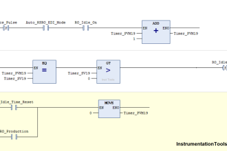
Interlock logic is represented by using AND Gates. In this case, if all the possible conditions are satisfied and active in the ON state, then the process starts and operates in safe mode.
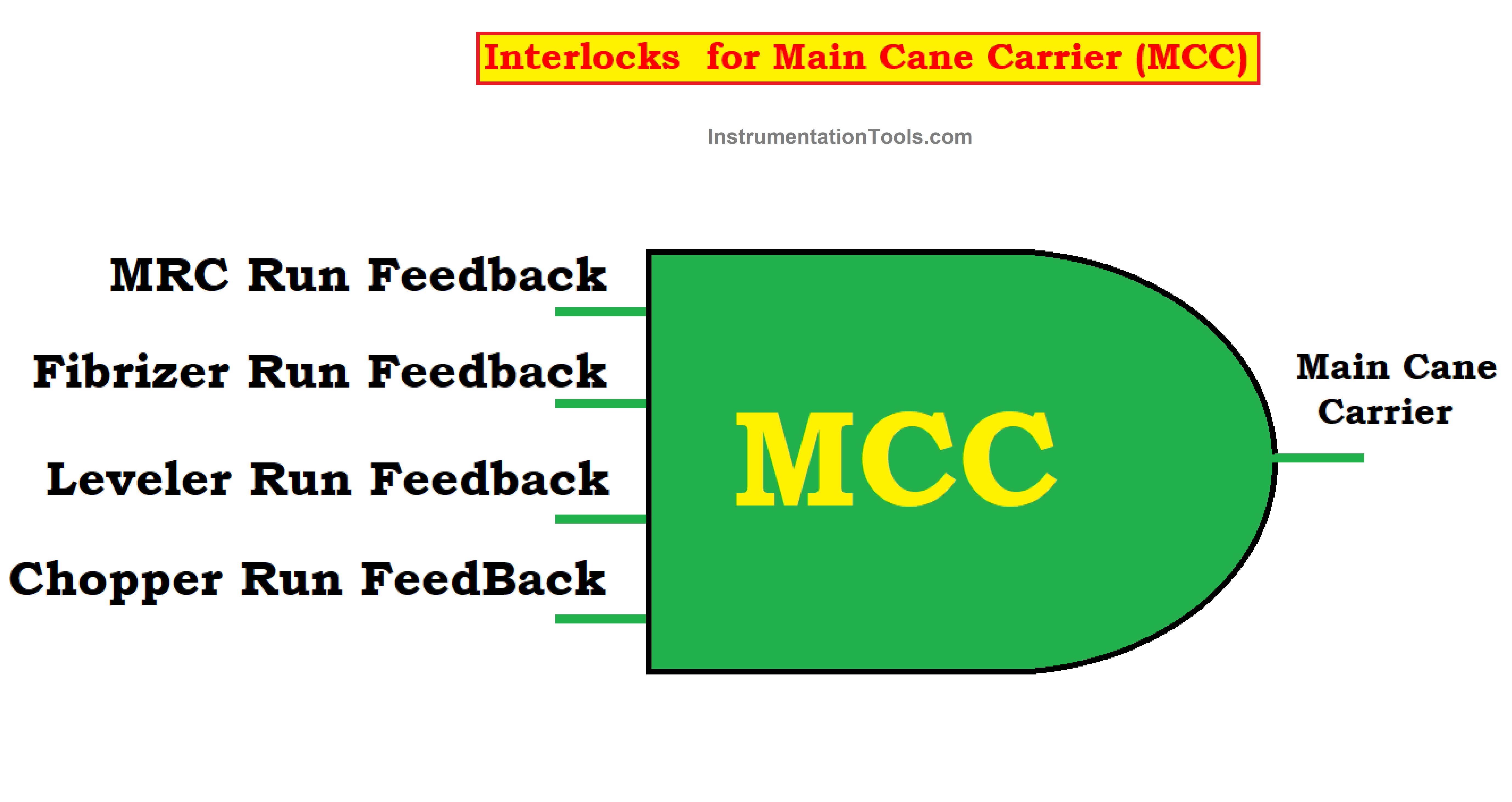
Interlocks for Main Cane Carrier (MCC)
The Main Cane Carrier Turns on if all the feedback is in on state.
- Chopper Run Feedback
- Leveler Run Feedback
- Fibrizer Run Feedback
- MRC Run Feedback
Interlock logic is represented by AND Gate
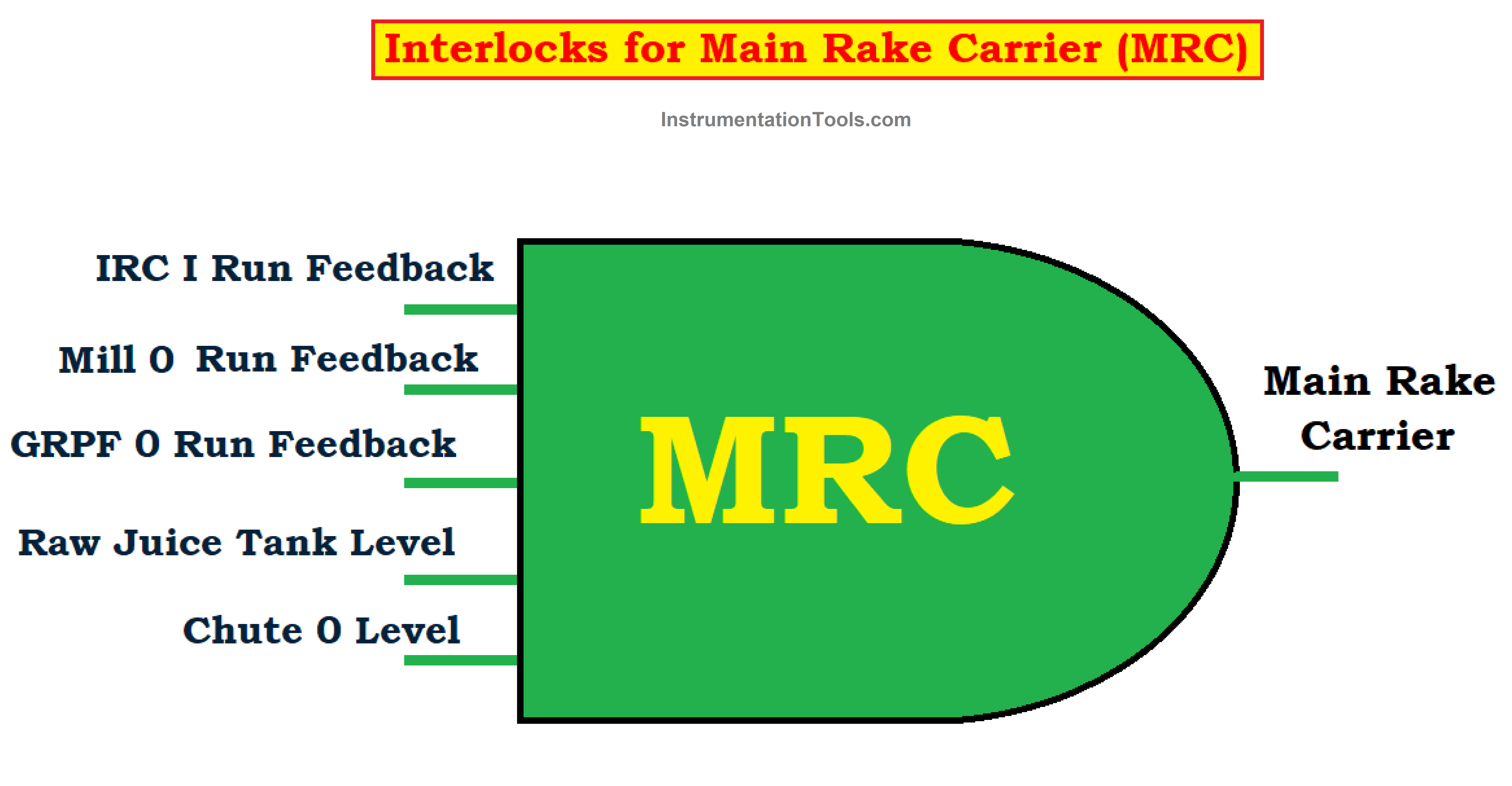
Interlocks for Main Rake Carrier (MRC)
The Main Rake Carrier Turns on if all the feedback is in on state.
- IRC I Run Feedback
- Chute 0 Level
- Mill 0 Run Feedback
- GRPF 0 Run Feedback
- Raw Juice Tank Level
The logic is represented as shown below.
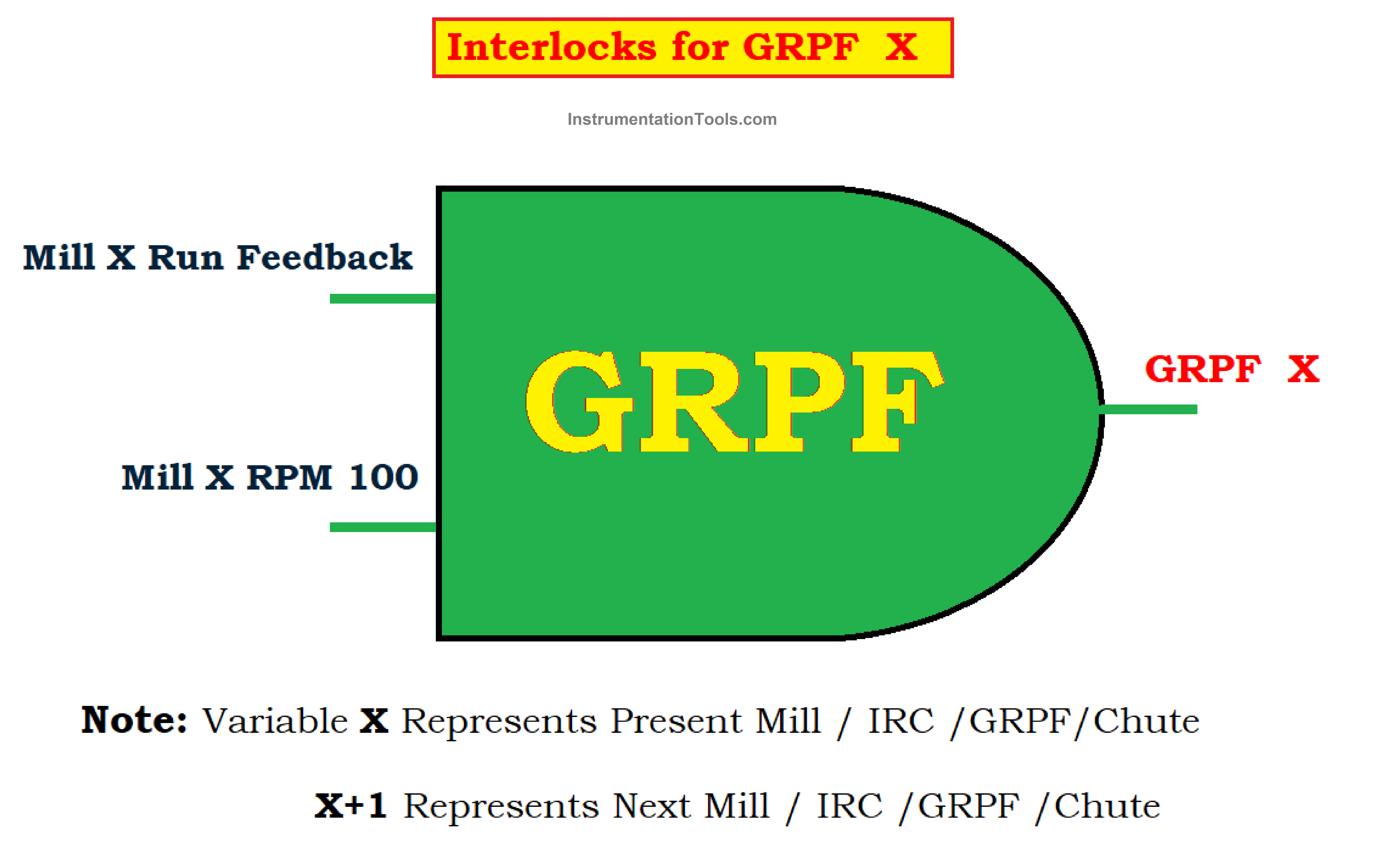
Interlocks for GRPF
The GRPF turns on if all the feedback is in on state if the Mill is started and the RPM of that mill must be greater than equal to 100 RPM
- Mill 0 Run Feedback
- Mill 0 RPM 100
GRPF is a Grooved Roller Pressure Feeder
Interlocks for Inter Rake Carrier I (IRC-I)
- IRC II Run Feedback
- Donnelly Chute I Level
- Mill I Run Feedback
- GRPF I Run Feedback
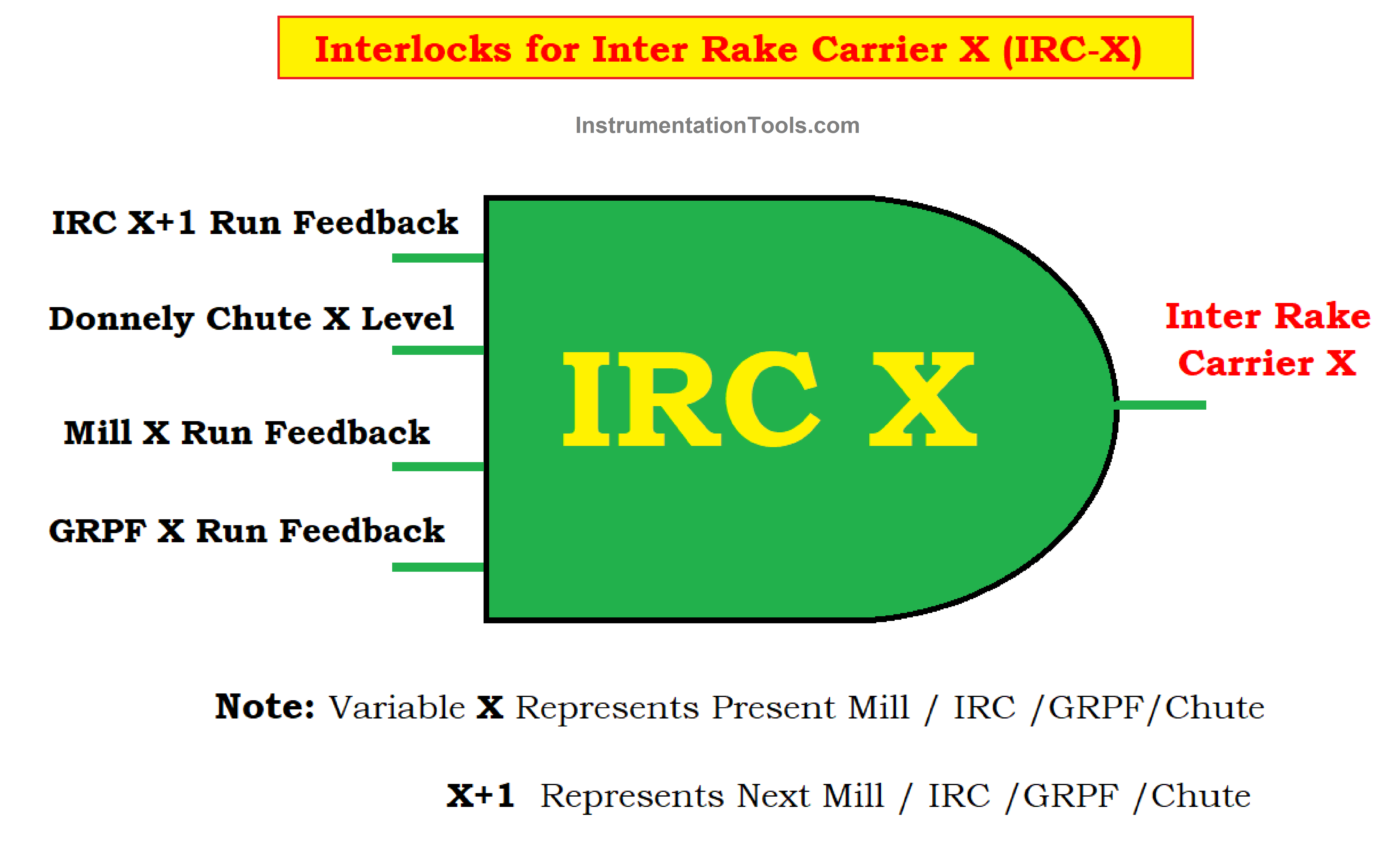
In the logic diagram, the X is used to represent the Mill number.
X = I, II, III, and IV for mill I to IV. And X+1 → Represents the next mill.
Interlocks for GRPF I
- Mill I Run Feedback
- Mill I RPM 100
Interlocks for Inter Rake Carrier II (IRC-II)
- IRC III Run Feedback
- Chute II Level
- Mill II Run Feedback
- GRPF II Run Feedback
Interlocks for GRPF II
- Mill II Run Feedback
- Mill II RPM 100
Interlocks for Inter Rake Carrier III (IRC-III)
- IRC IV Run Feedback
- Chute III Level
- Mill IV Run Feedback
- GRPF III Run Feedback
Interlocks for GRPF III
- Mill III Run Feedback
- Mill III RPM 100
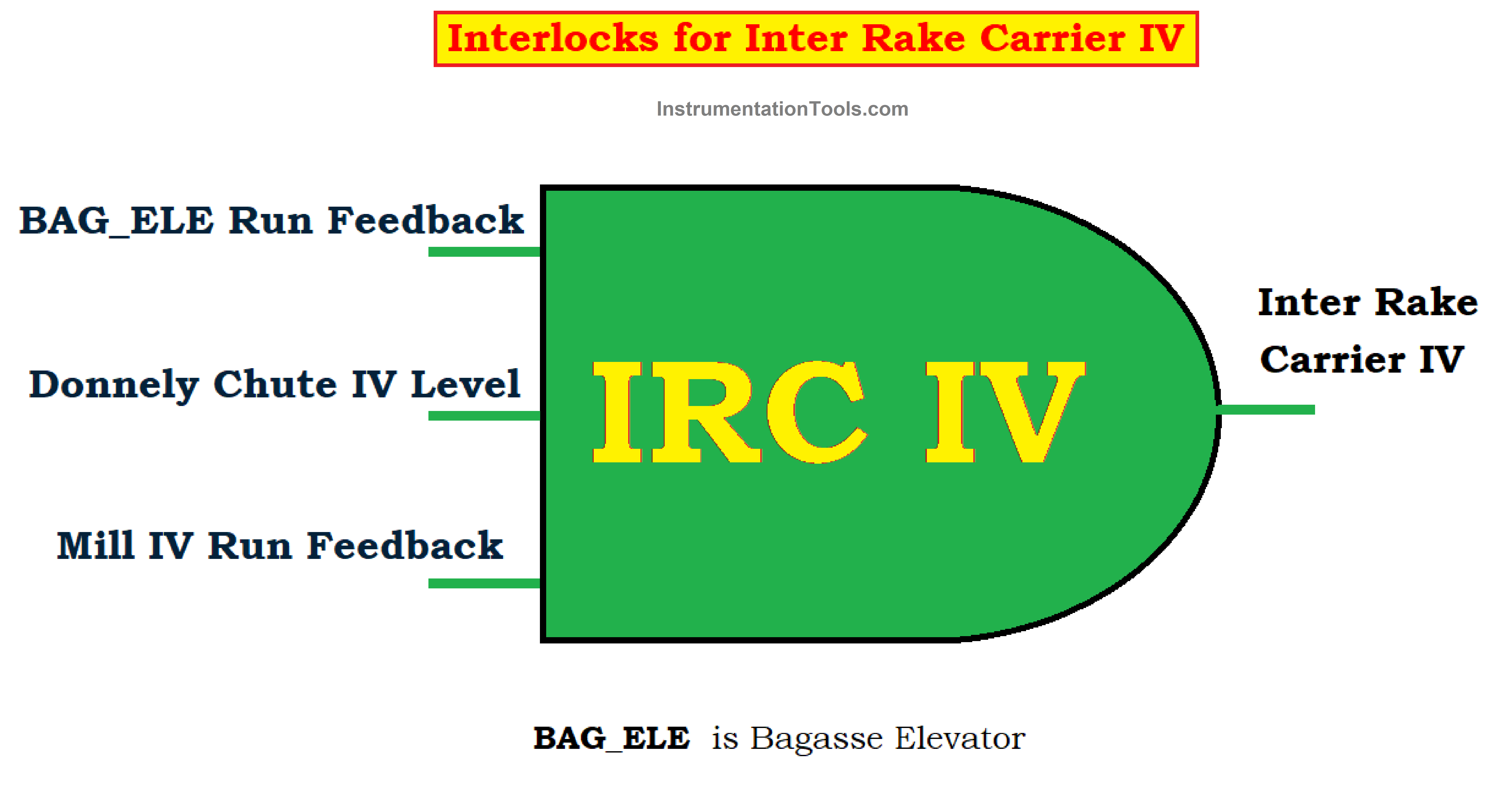
Interlocks for Inter Rake Carrier IV (IRC-IV)
- BAGELE Run feedback
- Chute IV Level
- Mill IV Run Feedback
The following conditions must be maintained
- The Run Feedback of all the devices Mill/ GRPF/ IRC /BAG_ELE must be active (High).
- If the raw juice tank level goes high above 90 % then the Main Cane Carrier speed is reduced manually to avoid the loss of extracted juice overflow, if there is no control over the juice tank level then the operator is instructed to turn off the MRC.
- The Donnelly Chute level at all the mills must be maintained to a predefined limit.
- If Donnelly Chute X level exceeds the predefined limit, then the status changes from green to red (low).
- To start GRPF the mill RPM must be 100 or more.
- In the case of safety interlocks if the bearing temperature of an individual mill drive goes high above the predefined limit the mill trips.
- The lubrication oil level must be maintained to the desired level.
- The hydraulic pressure of each mill at both crown and offside must be maintained to the desired value as shown in the below table.
| MILL | CROWN SIDE | OFF-SIDE |
| Mill 0 | 175 | 175 |
| Mill I | 99 | 148 |
| Mill II | 152 | 167 |
| Mill III | 167 | 138 |
| Mill IV | 0 | 273 |
Hydraulic Pressure in Kg/cm2


Wow. I like this. Inform me about Cane carrier ratio calculations in relation to production rates