Inst ToolsInst ToolsInst Tools
  • Courses
  • Automation
    • PLC
    • Control System
    • Safety System
    • Communication
    • Fire & Gas System
  • Instrumentation
    • Design
    • Pressure
    • Temperature
    • Flow
    • Level
    • Vibration
    • Analyzer
    • Control Valve
    • Switch
    • Calibration
    • Erection & Commissioning
  • Interview
    • Instrumentation
    • Electrical
    • Electronics
    • Practical
  • Q&A
    • Instrumentation
    • Control System
    • Electrical
    • Electronics
    • Analog Electronics
    • Digital Electronics
    • Power Electronics
    • Microprocessor
  • Request
Search
  • Books
  • Software
  • Projects
  • Process
  • Tools
  • Basics
  • Formula
  • Power Plant
  • Root Cause Analysis
  • Electrical Basics
  • Animation
  • Standards
  • 4-20 mA Course
  • Siemens PLC Course
Reading: Basic Pumping System Application Used in Industrial Automation
Share
Notification Show More
Font ResizerAa
Inst ToolsInst Tools
Font ResizerAa
  • Courses
  • Design
  • PLC
  • Interview
  • Control System
Search
  • Courses
  • Automation
    • PLC
    • Control System
    • Safety System
    • Communication
    • Fire & Gas System
  • Instrumentation
    • Design
    • Pressure
    • Temperature
    • Flow
    • Level
    • Vibration
    • Analyzer
    • Control Valve
    • Switch
    • Calibration
    • Erection & Commissioning
  • Interview
    • Instrumentation
    • Electrical
    • Electronics
    • Practical
  • Q&A
    • Instrumentation
    • Control System
    • Electrical
    • Electronics
    • Analog Electronics
    • Digital Electronics
    • Power Electronics
    • Microprocessor
  • Request
Follow US
All rights reserved. Reproduction in whole or in part without written permission is prohibited.
Inst Tools > Blog > PLC Tutorials > Basic Pumping System Application Used in Industrial Automation

Basic Pumping System Application Used in Industrial Automation

In this post, we will discuss the basic pumping system application that is used in industrial automation with PLC, VFD, and Motors.

Last updated: October 17, 2023 3:42 pm
Viral Nagda
PLC Tutorials
No Comments
Share
7 Min Read
SHARE

In this post, we will see the basic pumping system application that is used in industrial automation.

Contents
Pumping SystemSingle VFD SystemMulti VFD System

A pumping system is one of the widely used applications used in industrial automation.

Earlier, manual control was used where the operator had to go and start or stop the pumps according to pressure requirements from the user.

Pumping System

Basically, a pumping system in simpler terms can be viewed as the one used in your building. The society keeper (or watchman, or ourselves in our homes) controls the pump operation according to the flushing and domestic water requirements in the building.

Pumping System in Industrial Automation

Now, due to the use of PLC in the pumping systems, the manual intervention is reduced to a great extent, and also, the pressure control is achieved more accurately due to the use of automation.

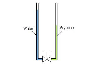
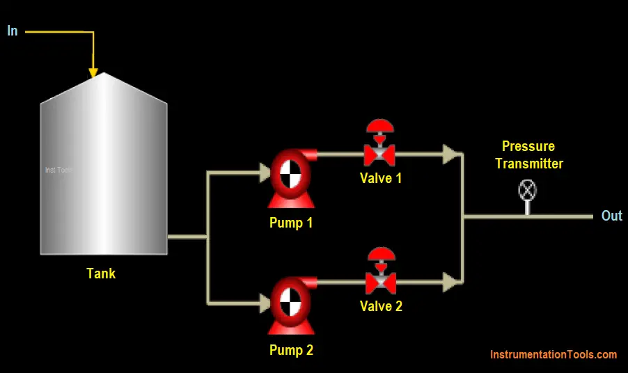
Refer to the above image. A typical pumping system used for domestic, commercial, and industrial purposes looks like this.

It consists of multiple pumps (depending upon pressure-demand design), its corresponding discharge valves, and a pressure transmitter.

The pumps use water from a common header line and control the flow of water to the discharge line by varying its motor speed, according to the pressure sensed at the discharge line.

The automatic control in pumping system can be classified into two types

  1. Single VFD and
  2. Multi VFD.

Single VFD System

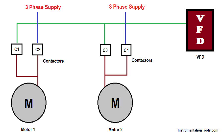
As the name suggests, this system consists of only a single VFD for multiple motors.

Refer to the below image.

Single VFD Control two motors

In this case, the PLC IO’s will be

  1. Digital inputs – VFD Trip feedback, Pump-1 VFD Contactor feedback, Pump-1 DOL Contactor feedback, Pump-2 VFD Contactor feedback, Pump-2 DOL Contactor feedback, Emergency Stop
  2. Digital Outputs – VFD Run Command, Pump-1 VFD Contactor, Pump-1 DOL Contactor, Pump-2 VFD Contactor, Pump-2 DOL Contactor
  3. Analog Inputs – Pressure Transmitter
  4. Analog Outputs – VFD Speed Reference

Now, let us see the control philosophy. There are three set points for the control

  1. cut- in pressure set,
  2. PID pressure set and
  3. cut-off pressure set.

When the pressure is below the cut-in set value, the pump with the least operating hours will operate first through the VFD contactor.

So, this pump speed will be controlled by VFD. If the pressure is still below the cut-in set value after a predefined time, then pump-2 will start through the DOL contactor.

As seen in the image, the DOL (Direct On-Line) contactor gets direct supply from the 3-phase incoming line, making the motor rotate at its full speed.

This logic ensures that any motor does not get supply from both the VFD and 3-phase direct simultaneously.

Otherwise, it will create a spark in the electrical circuit and the motor will get shorted; which can damage the environment or personnel standing nearby.

The pump VFD speed will be controlled based on PID. The PID takes the pressure sensor as input and the PID pressure set as set pressure.

When the pressure is below the setpoint, then the speed of VFD will increase gradually to reach its set point.

When the pressure goes above the setpoint, then the speed of VFD will decrease gradually to reach its set point. So, in short, the pressure will be tried to be maintained around the set point.

Now, when the pressure goes above the cut-off pressure set, then the DOL pump will turn off first. If the pressure is still above after a predefined time, then the VFD pump will turn off.

The cycle continues once the pressure drops again and the pump run management is done through its running hours which is calculated inside the PLC.

Pressure drop means demand is high and pressure increment means demand is low.

Through this, the running hours of both the pumps will be properly managed and also, there will not be any clash in operating of contactors.

If any pump trips in between, then the system will stop and the user has to press a reset button on a graphic display used; to restart the system once again.

Multi VFD System

It is a relatively easier system to design as compared to a single-VFD system. Each pump motor will have its individual VFD.

The only difference is that the second pump will operate at 50 Hz. This is in correlation with the DOL pump in a single-VFD system.

The electrical wiring is simpler as an individual motor will have only its single contactor for VFD output, as compared to dual contactors for a single motor in a single-VFD system.

In some systems, all the pumps work in PID. That means, all the pumps will run at the same speed because the pressure transmitter is one single only with the common set point.

This is the most common type of pumping system used in industrial automation. The design depends on user requirements. PLC logic too will differ depending upon the designer and his requirements.

If you liked this article, then please subscribe to our YouTube Channel for Instrumentation, Electrical, PLC, and SCADA video tutorials.

You can also follow us on Facebook and Twitter to receive daily updates.

Read Next:

  • Motor Speed Control using VFD
  • Problem on PLC, HMI, VFD, and Motor
  • PLC Simulator Mobile Apps
  • Compare Wifi and Industrial Wireless
  • Actuator Sensor Interface (ASi)
Don't Miss Our Updates
Be the first to get exclusive content straight to your email.
We promise not to spam you. You can unsubscribe at any time.
Invalid email address
You've successfully subscribed !

Continue Reading

Siemens PLC Mathematics Instructions
PLC Multiple Choice Questions
PLC SCADA Engineers Interview Questions and Answers
How to Create Faceplate in FactoryTalk View Studio?
Exhaust Fan Control: Example of PLC Timer Programming
Monitor and Modify Variables in Simatic Manager
Share This Article
Facebook Whatsapp Whatsapp LinkedIn Copy Link
Share
Leave a Comment

Leave a Reply Cancel reply

Your email address will not be published. Required fields are marked *

Stay Connected

128.3kFollowersLike
69.1kFollowersFollow
210kSubscribersSubscribe
38kFollowersFollow

Categories

Explore More

CODESYS HMI Interface
SCADA Multiple Choice Questions
PLC Programming for Sequential Batch Mixing System
System and Local Time in PLC
Various Causes for PLC Going in Stop Mode
Seven Segment Display Programming with Structured Text
Omron PLC Online Training Course
PLC Multiple Outputs Configuration

Keep Learning

PLC Program for Food Processing

PLC Program for Food Processing Industry

PLC Emergency Stop Example Program

PLC Emergency Stop Example Program

PLC Batch System for 4 Tanks Mixing using CX-Programmer

PLC Batch System for 4 Tanks Mixing using CX-Programmer

Examples of PLC Programming using Boolean Functions

Examples of PLC Programming using Boolean Functions

AI AO DI DO Signals

What are AI, AO, DI, and DO? – Definition, Examples, Purpose

Instrumentation During the Detail Design Phase

Instrumentation Engineer Activities & Documents – Detail Design Phase

Level Transmitter configuration in PLC

Scaling with Parameters (SCP) Instruction in PLC

Trolley and hoist PLC control

PLC Crane Movement Control with Limit Switches

Learn More

Mechanical Mini Projects

314 Mechanical Mini Projects List

Characteristics of Transducers Objective Questions

Characteristics of Transducers Objective Questions

Field Instruments Questions and Answers

Basics of Amplifiers Interview Questions

Sensors Objective Questions

Sensors Objective Questions

Pressure and Temperature Compensation for Flow Transmitter

Why Pressure & Temperature Compensation required for Orifice Flow Meters ?

Electrical Machines Questions and Answers

Autotransformers

Logic Gates Symbols & Truthtables

Logic Gates Animation

Illumination Objective Questions

Illumination Objective Questions

Menu

  • About
  • Privacy Policy
  • Copyright

Quick Links

  • Learn PLC
  • Helping Hand
  • Part Time Job

YouTube Subscribe

Follow US
All rights reserved. Reproduction in whole or in part without written permission is prohibited.
Welcome Back!

Sign in to your account

Username or Email Address
Password

Lost your password?