Inst ToolsInst ToolsInst Tools
  • Courses
  • Automation
    • PLC
    • Control System
    • Safety System
    • Communication
    • Fire & Gas System
  • Instrumentation
    • Design
    • Pressure
    • Temperature
    • Flow
    • Level
    • Vibration
    • Analyzer
    • Control Valve
    • Switch
    • Calibration
    • Erection & Commissioning
  • Interview
    • Instrumentation
    • Electrical
    • Electronics
    • Practical
  • Q&A
    • Instrumentation
    • Control System
    • Electrical
    • Electronics
    • Analog Electronics
    • Digital Electronics
    • Power Electronics
    • Microprocessor
  • Request
Search
  • Books
  • Software
  • Projects
  • Process
  • Tools
  • Basics
  • Formula
  • Power Plant
  • Root Cause Analysis
  • Electrical Basics
  • Animation
  • Standards
  • 4-20 mA Course
  • Siemens PLC Course
Reading: Liquid Level Control using Flow Loop
Share
Font ResizerAa
Inst ToolsInst Tools
Font ResizerAa
  • Courses
  • Design
  • PLC
  • Interview
  • Control System
Search
  • Courses
  • Automation
    • PLC
    • Control System
    • Safety System
    • Communication
    • Fire & Gas System
  • Instrumentation
    • Design
    • Pressure
    • Temperature
    • Flow
    • Level
    • Vibration
    • Analyzer
    • Control Valve
    • Switch
    • Calibration
    • Erection & Commissioning
  • Interview
    • Instrumentation
    • Electrical
    • Electronics
    • Practical
  • Q&A
    • Instrumentation
    • Control System
    • Electrical
    • Electronics
    • Analog Electronics
    • Digital Electronics
    • Power Electronics
    • Microprocessor
  • Request
Follow US
All rights reserved. Reproduction in whole or in part without written permission is prohibited.
Inst Tools > Blog > Control Systems > Liquid Level Control using Flow Loop

Liquid Level Control using Flow Loop

Last updated: March 12, 2020 12:26 pm
Editorial Staff
Control Systems
No Comments
Share
3 Min Read
SHARE

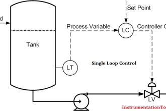
Since liquid level can only change in a vessel if there is an imbalance of inlet and outlet flow rates, would this system be practical to achieve steady liquid level control? Explain why or why not.

Level Control using Flow

Liquid Level Control using Flow Loop

Note: the philosophy behind this control system is a principle known as mass balance, and it is a very valid principle. Explain what the principle of “mass balance” is, and how it is implied in the design of this control system.

Also, mark the SP and PV inputs of the controller in this system with “+” and “−” symbols as appropriate to show the correct controller action.

Answer:

In theory, this feedforward system would work to hold the liquid level absolutely constant, because it will try to maintain flow out equal to flow in (mass out balances mass in).

However, there are some practical reasons why it would not work.

feedforward system example

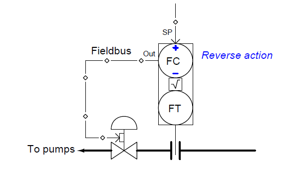
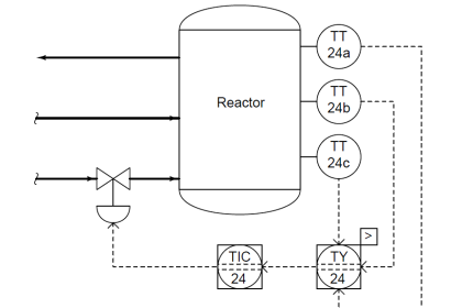
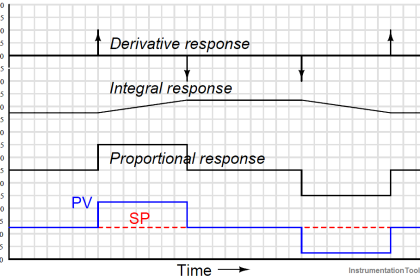
The controller needs to be reverse action, assuming a signal-to-open control valve:

The “+” symbol at the SP input of the controller tells us there is a non-inverting relationship between the SP input and the controller output. The “−” symbol at the PV input of the controller tells us there is an inverting relationship between the PV input and the controller output. Both of these characteristics are consistent with what we call “reverse” action in a loop controller.

Questions For You:

1. Explain why the control system as shown is impractical for real-life use, despite the fact that it does represent a very effective and important control strategy frequently used in industry.

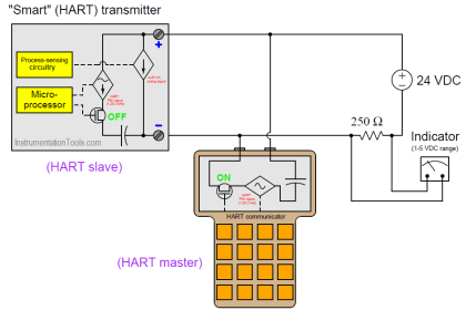
2. Explain what “Fieldbus” instruments are, and how they differ from traditional instrumentation.

3. How will this control system respond if the “wild” flow transmitter fails with a high signal?

4. How will this control system respond if the “drain” flow transmitter fails with a high signal?

5. How will this control system respond if the control valve’s air supply fails?

6. How will this control system respond if the “wild” flow line becomes partially plugged?

7. How will this control system respond if the “drain” flow line becomes partially plugged?

8. Are there any loads unaccounted for in this feedforward control strategy?

Join the Discussion! Share your answers with us through below comments section.

Read Next:

  • What is a Control Panel?
  • Question on Analytical Controller
  • Safe Practices
  • Displacer Level Sensor
  • Pressure Control Problems
Don't Miss Our Updates
Be the first to get exclusive content straight to your email.
We promise not to spam you. You can unsubscribe at any time.
Invalid email address
You've successfully subscribed !

Continue Reading

What is PV Tracking ?
Difference Between Serial and Parallel Communication
Control Systems Interview Questions & Answers
Instrumentation and Control Project Packages – Detail Engineering
What is Anti Surge System?
Concept of DCS in Industrial Automation
Share This Article
Facebook Whatsapp Whatsapp LinkedIn Copy Link
Share
Leave a Comment

Leave a Reply Cancel reply

Your email address will not be published. Required fields are marked *

Stay Connected

128.3kFollowersLike
69.1kFollowersFollow
210kSubscribersSubscribe
38kFollowersFollow

Categories

Explore More

Background of Modbus – ASCII and RTU Data Frames
Integral (Reset) Control Theory
How to Train Your Maintenance Team for Industrial Automation Systems?
Introduction to Control System
Five Levels in Industrial Automation
Stroke Checking Procedure for GCV, SRV, IGV, and LFBV
Tips for Reducing the Noise Signals
Ziegler-Nichols Open-Loop Method

Keep Learning

how-a-4-20ma-transmitter-works

How a 4-20mA Transmitter Works?

PROFIBUS is also a Master Slave protocol

Compare Modbus, Fieldbus, and Profibus

Basic Process Control System

Basic Process Control System

Inspection and Testing of Fiber Optic Cable

Inspection and Testing of Fiber Optic Cable

Types of Noise in Electronics

Types of Noise in Electronics

PLC or DCS Control System Spares

PLC or DCS Control System Spares

What is Data Acquisition

What is Data Acquisition? – Elements and Components

Field Instruments Questions and Answers

Control Room and Field Instruments Questions and Answers

Learn More

Power Electronics Objective Questions

SCR Commutation Objective Questions

DP-Flow-Transmitter-Re-Ranging-calculation

DP Flow Transmitter Re-Ranging Calculation

liquid flow control system

Practical Process Control System Questions & Answers – 7

Displacement Transducers Objective Questions

Displacement Transducers Objective Questions

Counters and Timers Projects Using Analog Electronic Devices

Top 100 Counters and Timers Projects Using Analog Electronic Devices

Belt Conveyor Weighing System

Belt Conveyor Weighing System – Weigh Bridge – Speed Sensor

PLC Program with 2 Toggle Switches and 4 Motors

PLC Program with 2 Toggle Switches and 4 Motors

Upgrading and Migration of PLC Systems

Upgrading and Migration of PLC Systems

Menu

  • About
  • Privacy Policy
  • Copyright

Quick Links

  • Learn PLC
  • Helping Hand
  • Part Time Job

YouTube Subscribe

Follow US
All rights reserved. Reproduction in whole or in part without written permission is prohibited.
Welcome Back!

Sign in to your account

Username or Email Address
Password

Lost your password?