A newly commissioned pressure control system has a problem: the controller registers a process fluid pressure of 22 PSI, but two pressure gauges connected to the same vessel both register 35 PSI.
A technician is sent to troubleshoot this problem and decides to measure current at terminal 2 of TB-52 (located in Field Panel JB-25). The current signal registers 15.2 milliamps DC:
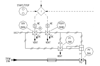
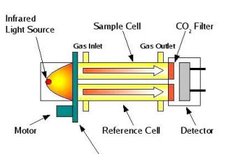
Pressure Control System

Based on these symptoms and information contained in this loop diagram, answer the following questions:
Where do you think the problem lies, and what sort of problem might it be?
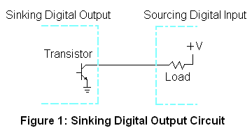
Sketch how the technician’s milliammeter should be connected in order to intercept the loop current at terminal 2 of TB-52. Include the test lead colors (red, black) in your answer.
Identify what steps the technician (or operator) should have done prior to taking the current measurement, to ensure nothing bad (e.g. process interruption, alarms) would happen when the circuit was broken to insert the milliammeter.
Modify both the transmitter and control valve 4-20 mA loop circuits to include diodes for the purpose of the convenient current measurement.
Solution:
15.2 milliamps correspond to 35 PSI in a 0-50 PSI transmitter range, which tells us the transmitter (PT-6) agrees with the two pressure gauges in saying that the process fluid pressure is 35 PSI. The fault, therefore, lies with the controller’s interpretation of this milliamp signal.
One possibility is that the controller input is mis-configured (e.g. LRV/URV values are set incorrectly). Another possibility is a ground fault (short to ground) in the black wire of cable 4 pair 1 or cable PT-6 at the controller input, shunting some of the 15.2 mA signals around the controller input so that the controller doesn’t see the full signal strength. One way to further diagnose the problem is to take a similar current measurement at terminal 12 of the analog input card.
The technician’s multimeter should be connected as a load: current (conventional flow) entering the red test lead, and current exiting the black test lead. Since current travels counter-clockwise in the transmitter loop, this means the red test lead will be on the left and the black test lead will be on the right.
The operator should place the controller into manual mode prior to any work being done on the transmitter circuit. If any PV alarms are configured on the controller, they should be temporarily disabled as well prior to doing the work.
Modified loop diagram containing diodes:

Share your Answers with us through comments.
Credits: Tony R. Kuphaldt
Read Next:
- Instrumentation Diagrams
- Loop Diagram Questions
- 4-20 mA Current Loop
- Pressure Control Loop
- Turbine Control System


The technician’s multimeter should be connected series at the terminal 12 in the control to read the 15.2 mA again if the multimeter read it. The problem will be either in the AI channel configuration or the AI card.
If the the 15.2 mA dropped in the terminal 12.so, the problem will be in one of the JBs may be a bad terminal block or cables between JBs.
Interesting website considering I&C refrech mind very technical educational you have all my regard.
First they need to check analog input card first by sending 4-20 mA using HART Comm to see if any issue occured inside the AI Card.
After that agree with Mohamed said .
Put the loop in manual . Drain the transmitter impulse lines for any choking and confirm that transmitter is reading correctly . We can check connecting pressure gauge in series. If the transmitter output is correct, check AI reads correctly and put loop in Auto.