Inst ToolsInst ToolsInst Tools
  • Courses
  • Automation
    • PLC
    • Control System
    • Safety System
    • Communication
    • Fire & Gas System
  • Instrumentation
    • Design
    • Pressure
    • Temperature
    • Flow
    • Level
    • Vibration
    • Analyzer
    • Control Valve
    • Switch
    • Calibration
    • Erection & Commissioning
  • Interview
    • Instrumentation
    • Electrical
    • Electronics
    • Practical
  • Q&A
    • Instrumentation
    • Control System
    • Electrical
    • Electronics
    • Analog Electronics
    • Digital Electronics
    • Power Electronics
    • Microprocessor
  • Request
Search
  • Books
  • Software
  • Projects
  • Process
  • Tools
  • Basics
  • Formula
  • Power Plant
  • Root Cause Analysis
  • Electrical Basics
  • Animation
  • Standards
  • 4-20 mA Course
  • Siemens PLC Course
Reading: TOC Analyzer Working Principle
Share
Notification Show More
Font ResizerAa
Inst ToolsInst Tools
Font ResizerAa
  • Courses
  • Design
  • PLC
  • Interview
  • Control System
Search
  • Courses
  • Automation
    • PLC
    • Control System
    • Safety System
    • Communication
    • Fire & Gas System
  • Instrumentation
    • Design
    • Pressure
    • Temperature
    • Flow
    • Level
    • Vibration
    • Analyzer
    • Control Valve
    • Switch
    • Calibration
    • Erection & Commissioning
  • Interview
    • Instrumentation
    • Electrical
    • Electronics
    • Practical
  • Q&A
    • Instrumentation
    • Control System
    • Electrical
    • Electronics
    • Analog Electronics
    • Digital Electronics
    • Power Electronics
    • Microprocessor
  • Request
Follow US
All rights reserved. Reproduction in whole or in part without written permission is prohibited.
Inst Tools > Blog > Analyzers > TOC Analyzer Working Principle

TOC Analyzer Working Principle

Last updated: November 14, 2017 10:02 am
Editorial Staff
Analyzers Animation
1 Comment
Share
3 Min Read
SHARE

Total Organic Carbon (TOC) measurement is commonly used to determine the degree of organic contamination in water.

Total Organic Carbon (TOC) is an indirect measure of organic molecules present in water and measured as carbon. Organic molecules are introduced into the water from the source water, from purification, and from distribution system materials. TOC is measured for both process control purposes and to satisfy regulatory requirements.

Analytical technologies utilized to measure TOC share the objective of completely oxidizing the organic molecules in an aliquot of sample water to carbon dioxide (CO2), measuring the resultant CO2 concentration, and expressing this response as carbon concentration. All technologies must discriminate between the inorganic carbon, which may be present in the water from sources such as dissolved CO2 and bicarbonate, and the CO2 generated from the oxidation of organic molecules in the sample.

One approach used to measure TOC involves subtracting the measured inorganic carbon (IC) from the measured total carbon (TC), which is the sum of organic carbon and inorganic carbon:

TOC = TC – IC.

TOC Technologies

The main difference between TOC technologies is how they oxidize organics.

All Total Organic Carbon (TOC) analyzers perform two functions: oxidizing organic carbon in water to CO2 and measuring the CO2 produced. What makes each TOC analyzer different is the method it uses to oxidize the organics in the water sample and the methods used to detect the resulting CO2.

Main Detection Methods

The three main methods of CO2 detection used commercially are:

  1. Non-dispersive infrared (NDIR)
  2. Direct Conductometric (Non-selective Conductometric)
  3. Membrane Conductometric Detection (Selective Conductometric)

NDIR TOC detectors measure CO2 in the gaseous phase, while conductometric TOC detectors measure CO2 in the liquid phase.

Non-Dispersive InfraRed (NDIR)

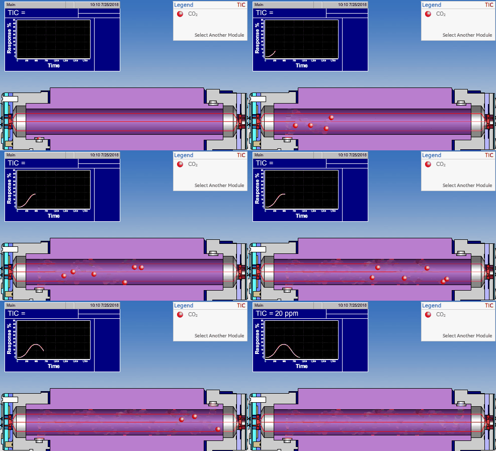
The non-dispersive infrared (NDIR) detector takes a preliminary  reading to determine a baseline.  When the sample enters the NDIR cell, the carbon dioxide molecules absorb the infrared light coming from the source, reducing the total transmittance of infrared light that reaches the detector. After all carbon dioxide has been removed from the cell, the percent transmittance returns to 100%.
TOC Analyzer Working Principle

Conductometric Technologies

Conductometric TOC detectors measure CO2 in the liquid phase. The two conductometric type detectors are Direct Conductometric and Membrane (or Selective) Conductometric. The two conductometric-type detectors have stable calibration and high sensitivity. The primary difference between the two conductometric types is that the direct detector is susceptible to interference from ionic contamination, acids, bases, and halogenated organics.

In the membrane-based conductometric method, the membrane is a protective barrier to interfering ions, enabling the analysis of CO2 only. The result is a more accurate TOC reading.
Don't Miss Our Updates
Be the first to get exclusive content straight to your email.
We promise not to spam you. You can unsubscribe at any time.
Invalid email address
You've successfully subscribed !

Continue Reading

Top 100 Analytical Instrumentation Engineering Projects
Ultrasonic Level Transmitter Animation
Open Loop and Closed Loop Animation
Magnetic Float Level Switch Working Animation
Bi-metal Temperature Sensors
Luft detector Principle
Share This Article
Facebook Whatsapp Whatsapp LinkedIn Copy Link
Share
1 Comment
  • teguig mahfoudh says:
    March 24, 2017 at 9:58 am

    i like this site so match, it’s a very good information about all instrumentation
    thank you my friend for your information
    i need some help about some problems about CO2 analyzer
    if you can help me with pleasure

    Reply

Leave a Reply Cancel reply

Your email address will not be published. Required fields are marked *

Stay Connected

128.3kFollowersLike
69.1kFollowersFollow
210kSubscribersSubscribe
38kFollowersFollow

Categories

Explore More

Online Simulation
Piston Flow Meters Working Principle with Animation
Specific Conductance Calibration Procedure
Oxygen (O2) Measurement in Flue Gas
Flame Ionization Detector (FID) Principle
Working Principle of Gas chromatograph
What is the Application of Electrical Conductivity Meter?
Kiln Inlet Gas Analyzer

Keep Learning

Relay Wiring

Animation of Electromagnetic Relay

Impeller Flow Sensor

Impeller Flow Sensor Working Principle and Animation

Vortex Flow Meter Animation

Basic Working Principle of Vortex Flowmeter

Oxygen Measurement using Tunable Diode Laser System

Tunable Diode Laser Analyzer Working Principle

Averaging Pitot Tube Working Principle

Pitot Tube Working Principle

Understanding the Scan Cycle of SIEMENS PLC

Understanding the Scan Cycle of SIEMENS PLC

Rotameters Working

Rotameter Working Principle and Animation

circuit-breaker-working-principle-animation

Circuit Breaker Working Principle Animation

Learn More

Structured Text PID control loop in PLC

How to Program PID Control in PLC with Structured Text?

What is Energy Monitoring System

What is Energy Monitoring System ?

Steam flow to the heat exchanger

Analytical Control System of Heat Exchanger Questions

Nuclear Magnetic Resonance Spectrometer Questions and Answers

Continuous Wave NMR Spectroscopy Questions & Answers

How to Connect HART Communicator with DP Transmitter

15 HART Communicator Questions

Distributed Control System Architecture

Control System Architecture

Measurement of Carbon Dioxide in Flue Gas

Measurement of Carbon Dioxide in Flue Gas

Portable Gas Detectors Calibration Procedure

Portable Gas Detectors Calibration Procedure

Menu

  • About
  • Privacy Policy
  • Copyright

Quick Links

  • Learn PLC
  • Helping Hand
  • Part Time Job

YouTube Subscribe

Follow US
All rights reserved. Reproduction in whole or in part without written permission is prohibited.
Welcome Back!

Sign in to your account

Username or Email Address
Password

Lost your password?