Instrumentation Diagrams Multiple Choice Questions
Question 1
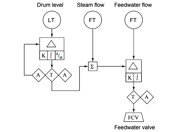
Identify what type of diagram this is:
(A) Wiring diagram
(B) Isometric drawing
(C) SAMA diagram
(D) P&ID
(E) Loop diagram
Answer : C
Question 2
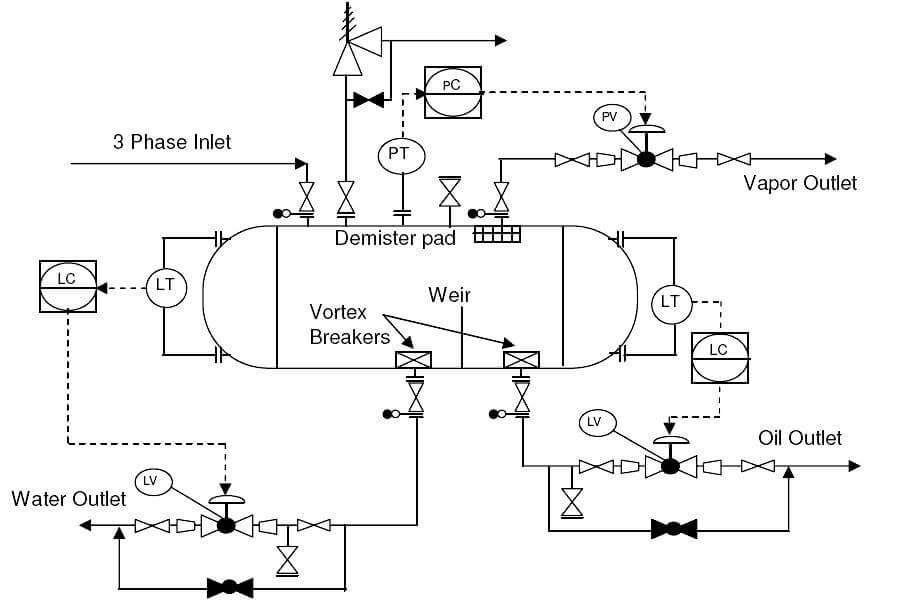
Identify what type of diagram this is:
(A) Wiring diagram
(B) Isometric drawing
(C) Loop diagram
(D) P&ID
(E) SAMA diagram
Answer : D
Question 3
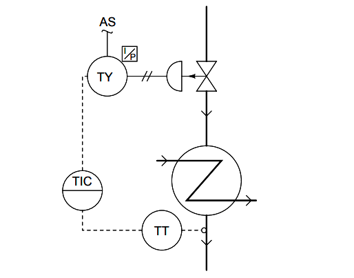
According to this diagram, the controller is , and it is located :
(A) Pneumatic, in the field (process) area
(B) Pneumatic, on the front of a secondary control panel
(C) Pneumatic, on the front of the main control panel
(D) Electronic, behind the main control panel
(E) Electronic, on the front of the main control panel
Answer : E
Question 4
Identify the following instrumentation (P&ID and loop diagram) line types, from left to right:
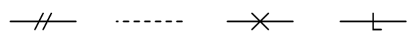
(A) pneumatic, electric, capillary, hydraulic
(B) electric, pneumatic, digital network, filled system
(C) pneumatic, electric, hydraulic, mechanical link
(D) electric (on/off), electric (analog), pneumatic, digital network
(E) pneumatic, mechanical link, hydraulic, capillary
Answer : A
Question 5
P&ID stands for ?
(A) Process & Information diagram
(B) Process & Instrumentation diagram
(C) Piping & Information drawings
(D) Piping & Instrumentation diagram
Answer : D
Question 6
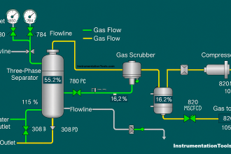
If the gas flow through FT-42 is 1200 SCFM, how much electric current is going through cable 23 and through cable 27 ?
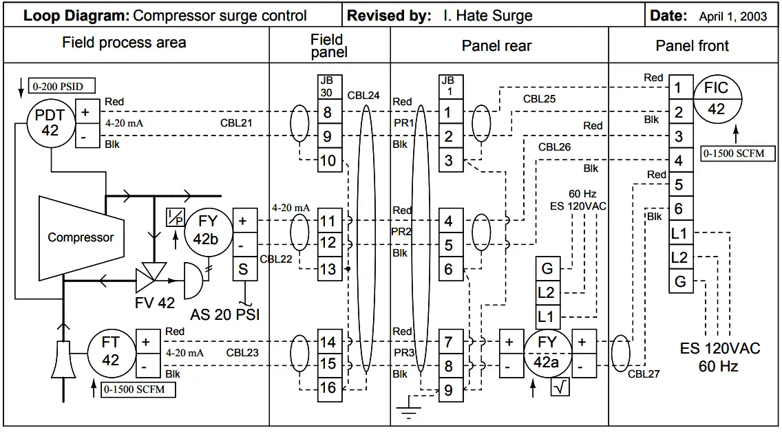
(A) ICBL23 = 14.2 mA , ICBL27 = 14.2 mA
(B) ICBL23 = 16.8 mA , ICBL27 = 16.8 mA
(C) ICBL23 = 16.8 mA , ICBL27 = 18.3 mA
(D) ICBL23 = 16.8 mA , ICBL27 = 14.2 mA
(E) ICBL23 = 14.2 mA , ICBL27 = 16.8 mA
Answer : E
Question 7
Calculate the voltage between terminals 15 and 16 of TB27 when the measured flow rate is 106 GPM.
Assume a loop power supply voltage of exactly 24.00 volts, and negligible wire resistance:
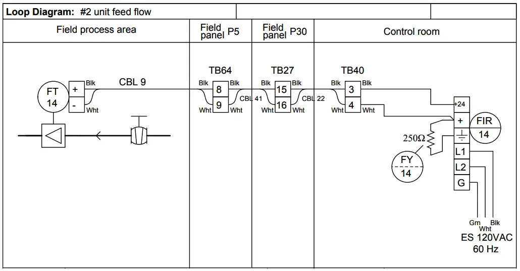
(A) 26.70 volts
(B) 22.28 volts
(C) 21.30 volts
(D) 24.00 volts
(E) 2.696 volts
Answer : C
Question 8
If the thermocouple fails open, what will happen?
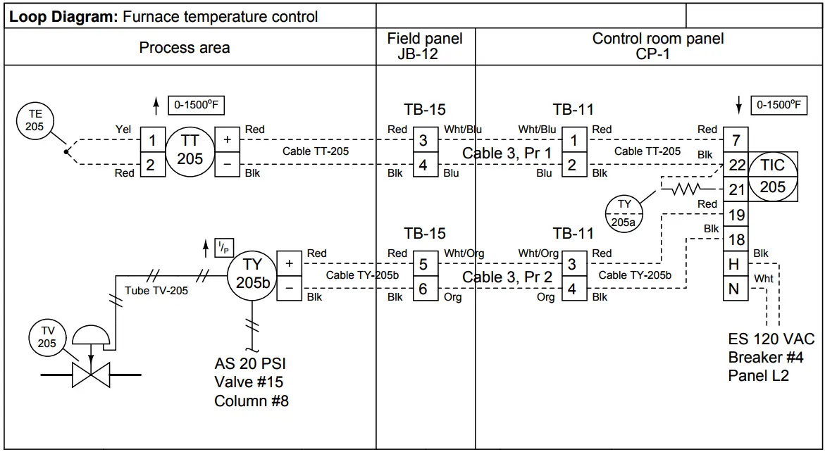
(A) Valve TV-205 will hold position, stabilizing the process
(B) Valve TV-205 will close shut, making the process cool down
(C) Valve TV-205 will close shut, making the process warm up
(D) Valve TV-205 will open wide, making the process cool down
(E) Valve TV-205 will open wide, making the process warm up
Answer : B
Question 9
What kind of device provides the setpoint for the analytical indicating controller in this diagram?
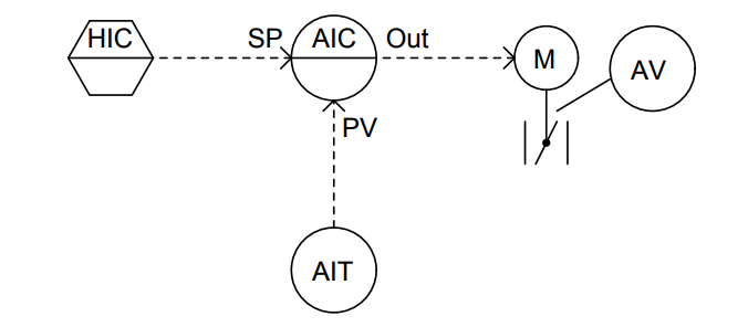
(A) A Workstation
(B) A mathematical relay
(C) Another panel-mounted controller
(D) A programmable logic controller (PLC)
(E) A pneumatic hand station
Answer : A
Question 10
What sort of alarm function is provided by the controller in this diagram?
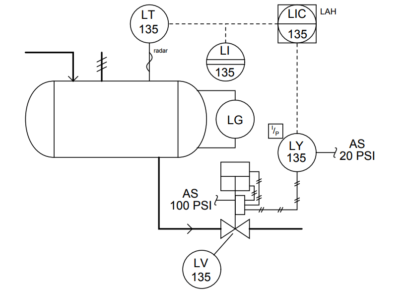
(A) Low-flow alarm
(B) High-temperature alarm
(C) Low-level alarm
(D) High-flow alarm
(E) High-level alarm
Answer : E
Credits : by Tony R. Kuphaldt


Question 6
You should have someone check the answer given.
Question 7
You are missing at least one piece of information to be able to arrive at an answer.
I agree with john question 6 answer is not correct , information is also not complete for question 6 & 7
Question 6:
I23 = 80%.16+4 = 16.8mA
I27 = Sqrt(80%).16+ 4 = 18.3 mA
So C is the correct answer not E ? Am I right ?
Yes, I agree!
Question 7: I think You should give the transmitter range (0 to 250) GPM
Can anyone please explain how to do the 8th and 11th questions?
In the 8th question, how are we determining whether the process is cooling down or warming up?
In the 11th question, I am confused how the valve positioner works.