Inst ToolsInst ToolsInst Tools
  • Courses
  • Automation
    • PLC
    • Control System
    • Safety System
    • Communication
    • Fire & Gas System
  • Instrumentation
    • Design
    • Pressure
    • Temperature
    • Flow
    • Level
    • Vibration
    • Analyzer
    • Control Valve
    • Switch
    • Calibration
    • Erection & Commissioning
  • Interview
    • Instrumentation
    • Electrical
    • Electronics
    • Practical
  • Q&A
    • Instrumentation
    • Control System
    • Electrical
    • Electronics
    • Analog Electronics
    • Digital Electronics
    • Power Electronics
    • Microprocessor
  • Request
Search
  • Books
  • Software
  • Projects
  • Process
  • Tools
  • Basics
  • Formula
  • Power Plant
  • Root Cause Analysis
  • Electrical Basics
  • Animation
  • Standards
  • 4-20 mA Course
  • Siemens PLC Course
Reading: Pressure based Flow Meters
Share
Font ResizerAa
Inst ToolsInst Tools
Font ResizerAa
  • Courses
  • Design
  • PLC
  • Interview
  • Control System
Search
  • Courses
  • Automation
    • PLC
    • Control System
    • Safety System
    • Communication
    • Fire & Gas System
  • Instrumentation
    • Design
    • Pressure
    • Temperature
    • Flow
    • Level
    • Vibration
    • Analyzer
    • Control Valve
    • Switch
    • Calibration
    • Erection & Commissioning
  • Interview
    • Instrumentation
    • Electrical
    • Electronics
    • Practical
  • Q&A
    • Instrumentation
    • Control System
    • Electrical
    • Electronics
    • Analog Electronics
    • Digital Electronics
    • Power Electronics
    • Microprocessor
  • Request
Follow US
All rights reserved. Reproduction in whole or in part without written permission is prohibited.
Inst Tools > Blog > Flow Measurement > Pressure based Flow Meters

Pressure based Flow Meters

Pressure based Flow Meters like differential pressure transmitters are used to measure the pressure drop to calculate equivalent flow rate.

Last updated: November 1, 2023 3:51 pm
Editorial Staff
Flow Measurement
2 Comments
Share
6 Min Read
SHARE

All masses require force to accelerate (we can also think of this in terms of the mass generating a reaction force as a result of being accelerated).

Contents
Basics of Flow MetersPressure-based Flow Meters

This is quantitatively expressed by Newton’s Second Law of Motion.

Basics of Flow Meters

What is Pressure

All fluids possess mass and therefore require force to accelerate just like solid masses.

If we consider a quantity of fluid confined inside a pipe, with that fluid quantity having a mass equal to its volume multiplied by its mass density (m = ρV , where ρ is the fluid’s mass per unit volume), the force required to accelerate that fluid “plug” would be calculated just the same as for a solid mass:

What is Flow

Since this accelerating force is applied on the cross-sectional area of the fluid plug, we may express it as a pressure, the definition of pressure being force per unit area:

force per unit area

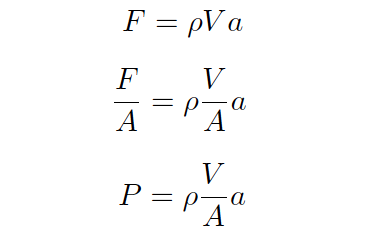
Since the rules of algebra required we divide both sides of the force equation by area, it left us with a fraction of volume over area (V/A) on the right-hand side of the equation.

This fraction has a physical meaning, since we know the volume of a cylinder divided by the area of its circular face is simply the length of that cylinder:

force per unit area - 1

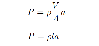
When we apply this to the illustration of the fluid mass, it makes sense: the pressure described by the equation is actually a differential pressure drop from one side of the fluid mass to the other, with the length variable (l) describing the spacing between the differential pressure ports:

differential pressure drop

This tells us we can accelerate a “plug” of fluid by applying a difference of pressure across its length.

The amount of pressure we apply will be in direct proportion to the density of the fluid and its rate of acceleration. Conversely, we may measure a fluid’s rate of acceleration by measuring the pressure developed across a distance over which it accelerates.

We may easily force a fluid to accelerate by altering its natural flow path. The difference of pressure generated by this acceleration will indirectly indicate the rate of acceleration.

Since the acceleration we see from a change in flow path is a direct function of how fast the fluid was originally moving, the acceleration (and therefore the pressure drop) indirectly indicates fluid flow rate.

A very common way to cause linear acceleration in a moving fluid is to pass the fluid through a constriction in the pipe, thereby increasing its velocity (remember that the definition of acceleration is a change in velocity).

Pressure-based Flow Meters

The following illustrations show several devices used to linearly accelerate moving fluids when placed in pipes, with differential pressure transmitters connected to measure the pressure drop resulting from this acceleration:

Pressure based Flow Meters

Read the detailed topics on below flow meters:

  • Venturi
  • Orifice
  • V Cone
  • Flow Nozzle
  • Segmental Wedge

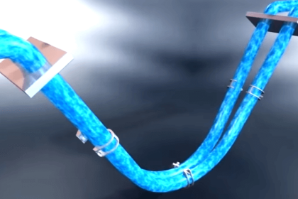
Another way we may accelerate a fluid is to force it to turn a corner through a pipe fitting called an elbow.

This will generate radial acceleration, causing a pressure difference between the outside and inside of the elbow which may be measured by a differential pressure transmitter:

pressure difference at the pipe elbow

Note : we do not use this type of installation for flow measurement in real world

The pressure tap located on the outside of the elbow’s turn registers a greater pressure than the tap located on the inside of the elbow’s turn, due to the inertial force of the fluid’s mass being “flung” to the outside of the turn as it rounds the corner.

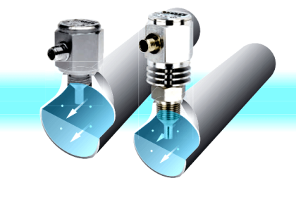
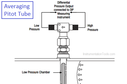
Yet another way to cause a change in fluid velocity is to force it to decelerate by bringing a portion of it to a full stop. The pressure generated by this deceleration (called the stagnation pressure) tells us how fast it was originally flowing.

A few devices working on this principle are shown here:

Flow Meters

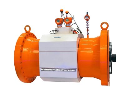
Different primary sensing elements (PSE’s) used to generate differential pressure in a moving fluid stream.

  • Pitot Tube
  • Annubar
  • Averaging Pitot Tube
  • Target Flow Meter

Despite their very different designs, they all operate on the same fundamental principle: causing fluid to accelerate or decelerate by forcing a change in its flow path, and thus generating a measurable pressure difference.

If you liked this article, then please subscribe to our YouTube Channel for Electrical, Electronics, Instrumentation, PLC, and SCADA video tutorials.

You can also follow us on Facebook and Twitter to receive daily updates.

Read Next:

  • DP Flow Calculations
  • Flow Measuring Devices
  • Wedge Flow Meter Principle
  • Mass Flow Calculations
  • Vortex Flow Meter Animation
Don't Miss Our Updates
Be the first to get exclusive content straight to your email.
We promise not to spam you. You can unsubscribe at any time.
Invalid email address
You've successfully subscribed !

Continue Reading

Oval Gear Meter – Principle, Advantages, Limitations, Applications
Turbine Flow Meters Troubleshooting
Basics of Flow Measurement
Troubleshooting DP type Transmitter Common Problems
What is a Torbar? – Averaging Pitot Tubes
Flow Meter Installation Guidelines
Share This Article
Facebook Whatsapp Whatsapp LinkedIn Copy Link
Share
2 Comments
  • Rajesh Das says:
    January 2, 2018 at 2:32 pm

    Sir , Also include calibration of Circular flow recorder

    Reply
  • PRASANTH says:
    September 5, 2018 at 8:08 pm

    Can venturi flowmeter detect reverse flow. What configuration is needed in transmitter and DCS. Please clarify

    Reply

Leave a Reply Cancel reply

Your email address will not be published. Required fields are marked *

Stay Connected

128.3kFollowersLike
69.1kFollowersFollow
210kSubscribersSubscribe
38kFollowersFollow

Categories

Explore More

Difference between Invasive, Non-invasive, Intrusive & Non-intrusive
DP Flow Transmitter Re-Ranging Calculation
Types of Vortex Flow Meter Sensors
Working Principle of Flow Switch with Animation
What is a Condensate Pot? How to Install it?
Turbine Flow Meter – Principle, Advantages, Disadvantages
All About Vortex Flow Meters
Multiphase Flow Meter Calibration Procedure

Keep Learning

Rotameters Working

Rotameter Working Principle and Animation

What is an Orifice Flange ?

What is an Orifice Flange? – Purpose and Applications

Step by step guide for Gas Flow Meter Calibration

Step by Step Guide for Gas Flow Meter Calibration

Coriolis Mass Flow meter as a Multi Variable Transmitter - 1

Coriolis Mass Flow Meter as a Multi-Variable Transmitter

Coriolis Mass Flow Meter Working Animation

Coriolis Meter Explained with Animation

Orifice Flow Meter With DP Transmitter

What is an Orifice Meter?

Vortex Flow Meter Principle

Vortex Flow meter Animation

Flow meter Turndown Ratio

Why Turndown Ratio is important when Selecting a Flow Meter?

Learn More

Siemens PLC Math Instructions

Siemens PLC Mathematics Instructions

Resistive Transducers Objective Questions

Resistive Transducers Objective Questions

Rectifiers & Filters Interview Questions

Rectifiers & Filters Interview Questions

Bubbler Level Measurement Animation

Bubbler Level Measurement Animation

How to calculate Thermocouple Temperature by measuring the output millivoltage

Power Electronics Objective Questions

Thyristor Family Objective Questions and Answers

Magnetic Float Level Switch Principle

Magnetic Float Level Switch Installation Techniques

Power Systems Questions & Answers

Power Systems MCQ Series 16

Menu

  • About
  • Privacy Policy
  • Copyright

Quick Links

  • Learn PLC
  • Helping Hand
  • Part Time Job

YouTube Subscribe

Follow US
All rights reserved. Reproduction in whole or in part without written permission is prohibited.
Welcome Back!

Sign in to your account

Username or Email Address
Password

Lost your password?