This article is about controlling the Pneumatic cylinder and Pneumatic motor in the assembly line for fixing applications.
Pneumatic Cylinder and Motor
Pneumatic operation is one of the easy, fast, and reliable functions in automotive & manufacturing. Mostly, all the fasteners fixing applications in the manufacturing sectors use pneumatic operation because of its easy functions and safe operation.
Now, in our process, we are using both the pneumatic actuators, Pneumatic Cylinders, and Pneumatic motors in the assembly line for the assembly operations. The pneumatic Cylinder is for clamping and the Pneumatic Motor is for fixing/tightening.
This is a semi-automatic process, which means once the component is placed on the base, the Pneumatic cylinder clamps the component, and once the component is clamped and the Pneumatic motor is actuated it will rotate and fix the necessary as per the setting. We have used the timer to set the time required for fixing the components.
Components Used:
Air Compressor
Air compressor is a machine that is the air supply unit for the whole pneumatic system. This compressor compresses air from a low inlet pressure to a higher desired pressure level. The changes of pressure from lower to higher levels are achieved by reducing the volume of the gas.
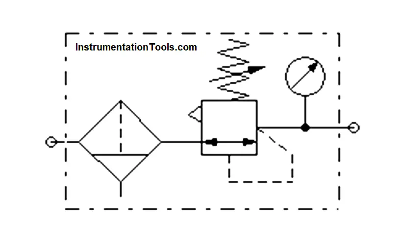
FRL unit
This FRL unit is used to make air a more acceptable medium for the operating system. FRL stands for Filter, Regulator, and Lubricator. All three units have separate functions and capabilities. Filter is used to remove contaminants from the air before it reaches the pneumatic components.
A regulator is used for setting and controlling the constant pressure for the system. A lubricator is used for providing suitable lubrication for internal moving parts of pneumatic components.
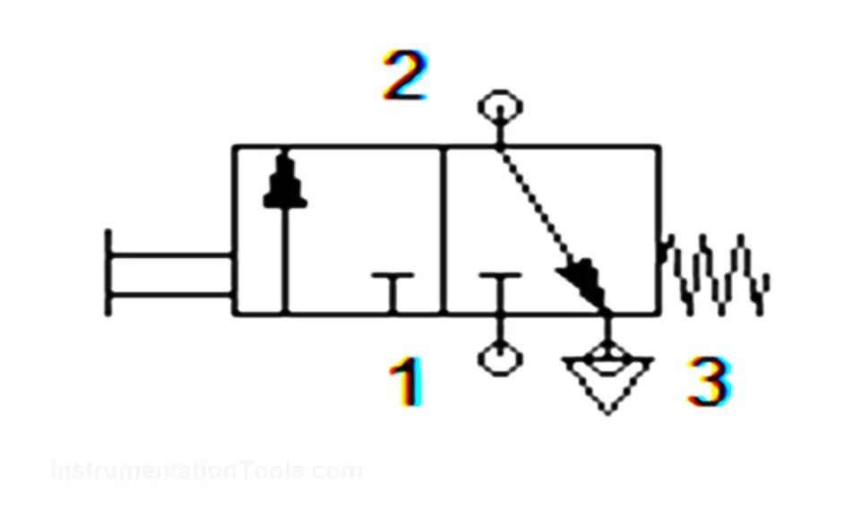
3/2 Push Button Actuated Direction Controlled Valve
A 3/2 Push button valve is used to control the direction of the air supply by mechanical actuation.
In this 3 denotes the number of ports and 2 denotes the number of moving positions.
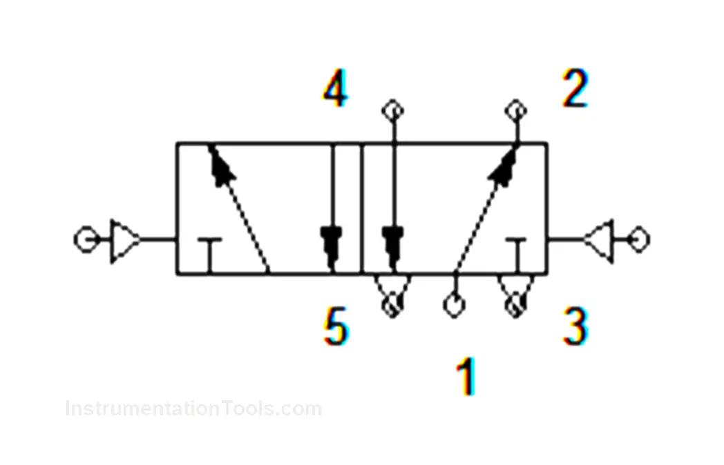
5/2 Pilot Activated Actuated Direction Controlled Valve
5/2 Pilot activated direction control valve is also used to control the direction of the pneumatic supply but its position movement is done by the control supply itself, it does not require any mechanical or manual actuation support.
In this 5 denotes the number of ports and 2 denotes the number of positions.
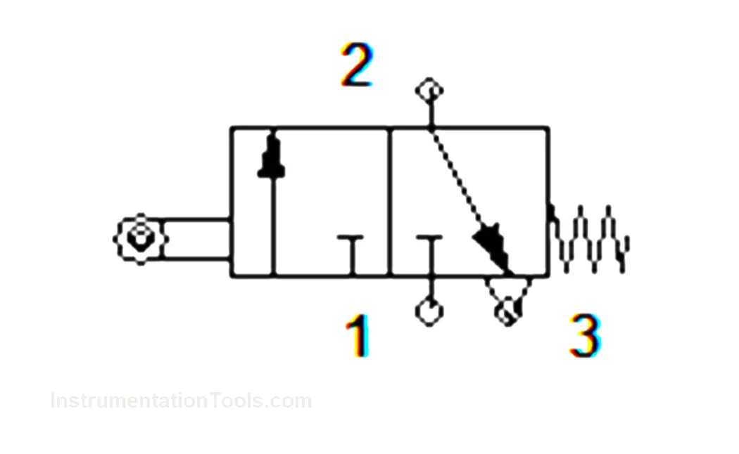
3/2 Roller Actuated Direction Controlled Valve
3/2 Roller actuated valve control the direction of supply by actuating the roller at the end. It is the same as the limit switch in electrical.
Once the roller is engaged it actuates the operation.
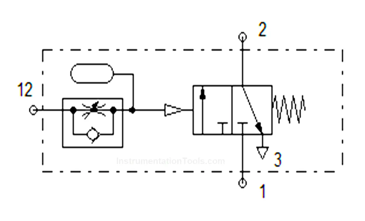
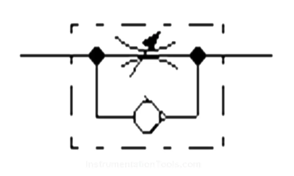
Pneumatic ON Delay Timer Valve
A pneumatic Timer Valve is used to control the actuation with some delay.
In this, we are using an ON Delay Timer which will operate with some delay after receiving the signal.
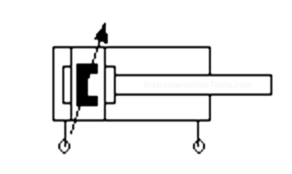
Pneumatic Double Acting Cylinder
A double-acting cylinder is an actuator that moves in both forward and reverse directions after getting the signal through two ports.
One port is for forward motion and another port is for reverse motion.
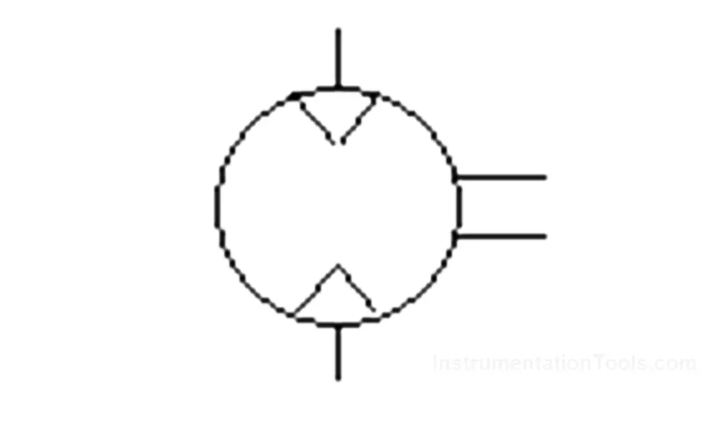
Pneumatic Air Motor
An air motor is a device that usually transforms pneumatic energy into rotary mechanical motion to perform useful work. These motors can be of the limited rotation or the continuous rotation type.
Based on the application we can select the type.
Flow Control Valve
A Flow control valve allows free flow in one direction and an adjustable or controlled flow in other side direction.
Flow control is adjusted by the knob that controls the flow that enters into the actuator.
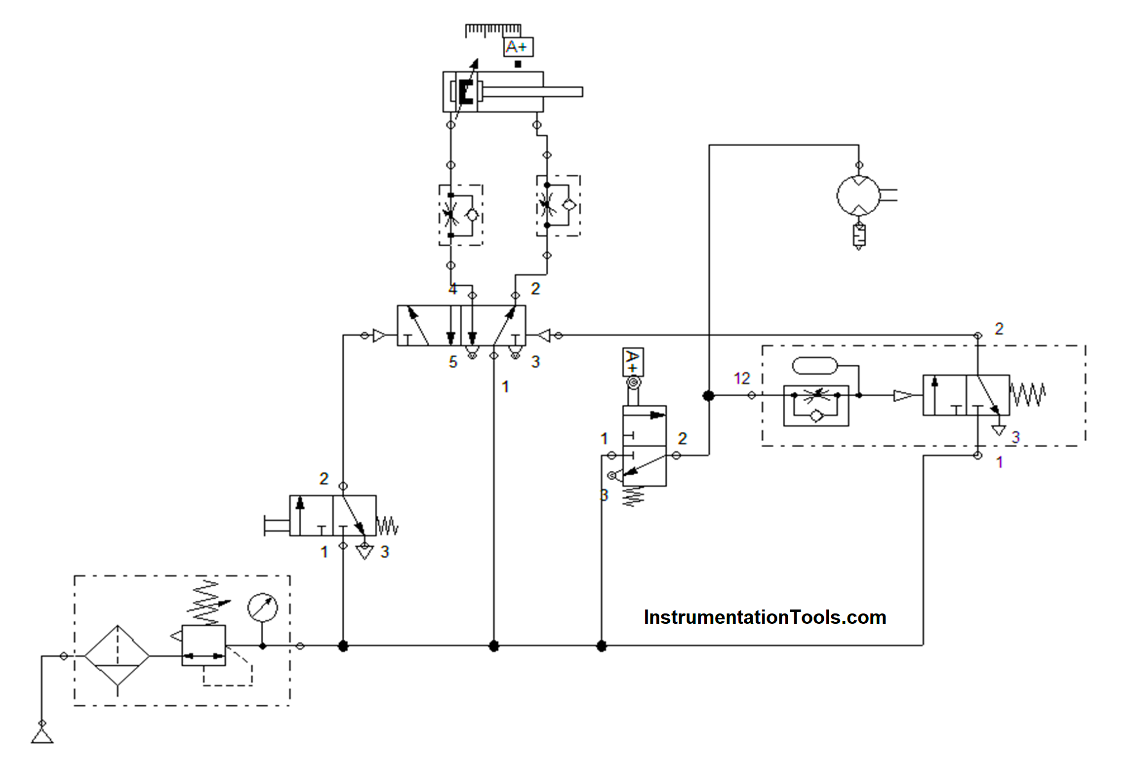
Circuit Diagram
Working Principle
Compressed air of 4 – 6 bar is given to the system with the help of a compressor. Air supply entered into the system by getting into the FRL unit for removing the dust, for stable air supply, and for the friction of internal parts of the actuators.
Then the 3/2 Direction Controlled Push button is pressed manually and the air direction changes through the ports and enters into the 5/2 Direction control Pilot valve which makes the cylinder to move forward. The flow enters to the cylinder can be adjusted with the help of Flow Control as per the requirement
Once the cylinder is actuated forward, it touches the roller valve at its end position. This forward movement of the cylinder is clamping the component. Once it is clamped, it gives the signal through the roller valve for the motor. Then the motor starts to rotate. This rotation is considered as the fixing of the component (Tightening).
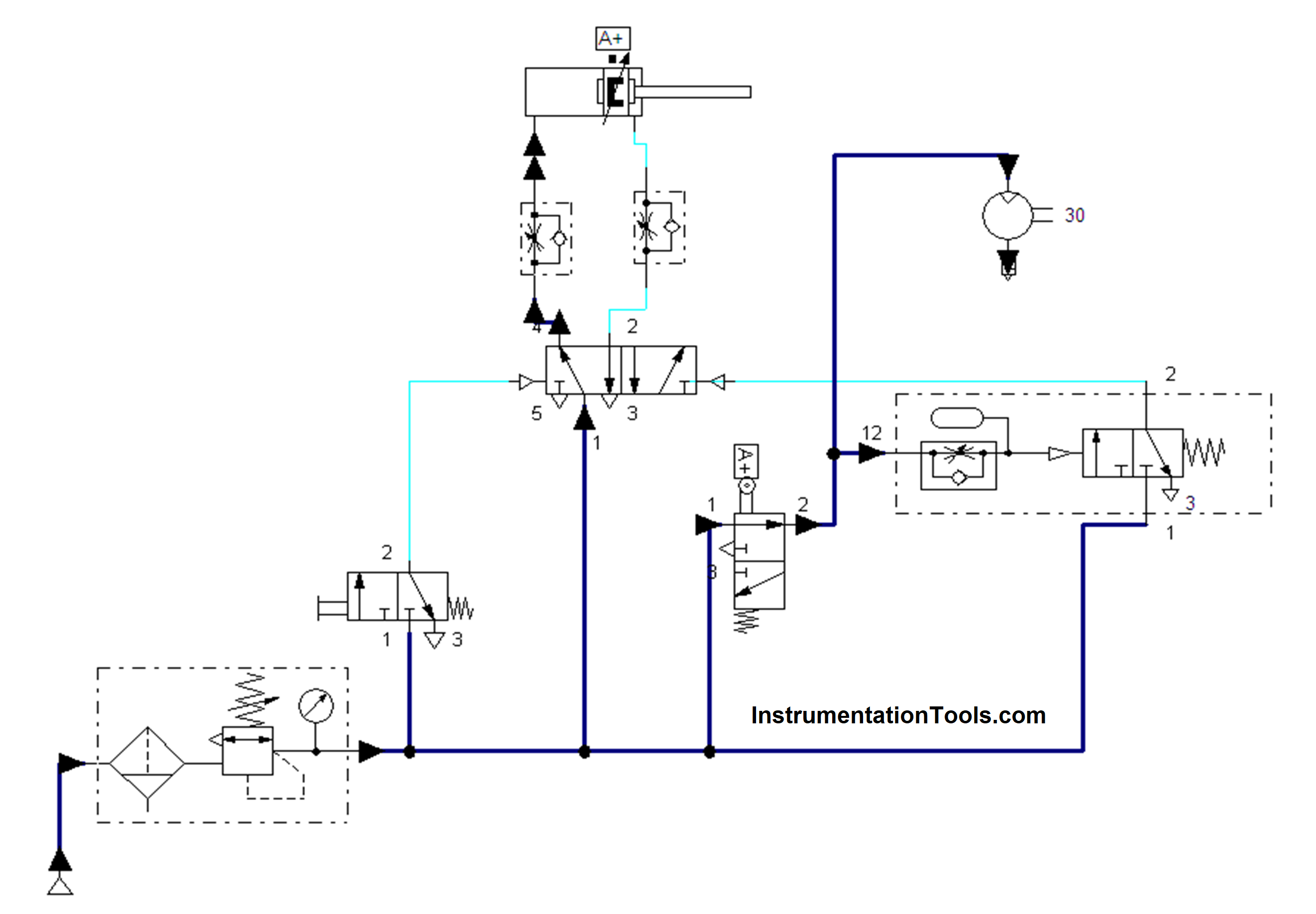
The motor will rotate only for a certain time as per the requirement.
The required time is marked in the timer depending on that it will actuate the timer and after the set time it will give the signal to the 5/2 directional pilot actuated valve which makes the cylinder to move backwards and at the same time motor will also stop its rotation. This will be considered as the de-clamp of the component.
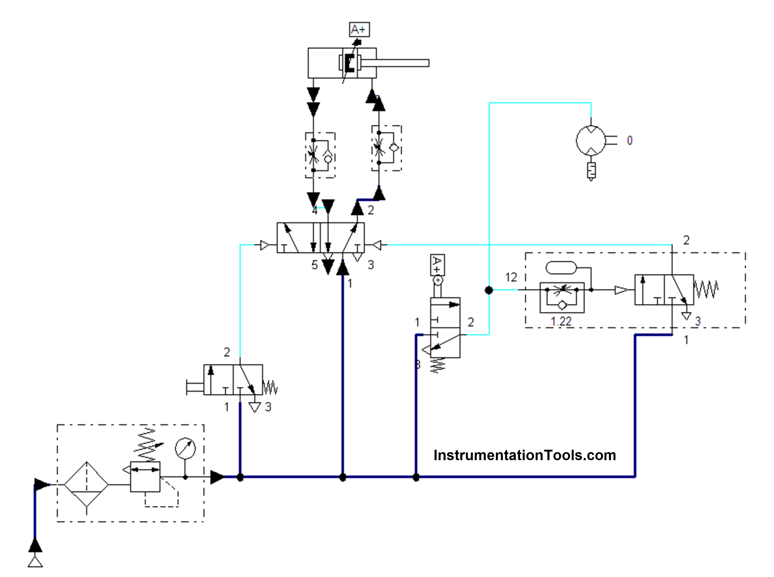
This process will continue for each component and it will makes the worker easier and efficient way in the assembly for clamping and fixing. Depending on the requirement we can change the timer settings and flow settings in the flow control valve by adjusting the knob on both the timer valve and the flow control valve.
Read Next:
- What is a Pneumatic Cylinder?
- Pneumatic Valves and Cylinders Sizing
- Proximity Switch Working Animation
- Free Cylinder Valve Sizing Calculator
- Sequential PLC Program Pneumatic Valve