It is possible to divide the world of electronics into two main categories – Digitals electronics and Power electronics. Nowadays, most modern electronic devices such as mobile phones and computers work with digital electronics.
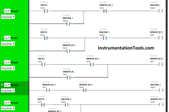
Even though digital electronics have many applications, they are mostly used for industrial automation. One warehouse organization needs discrete values for the machines, so digital electronics are used to get them and run the circuit.
To be honest, digital electronics are part of our daily life. Electronics are used in everything from watches to fitness bands to automatic glass doors in airports, malls, and metro stations.
In this article, we are providing three ideas, for those who are interested to do digital electronics projects.
Simple Electronic Piano
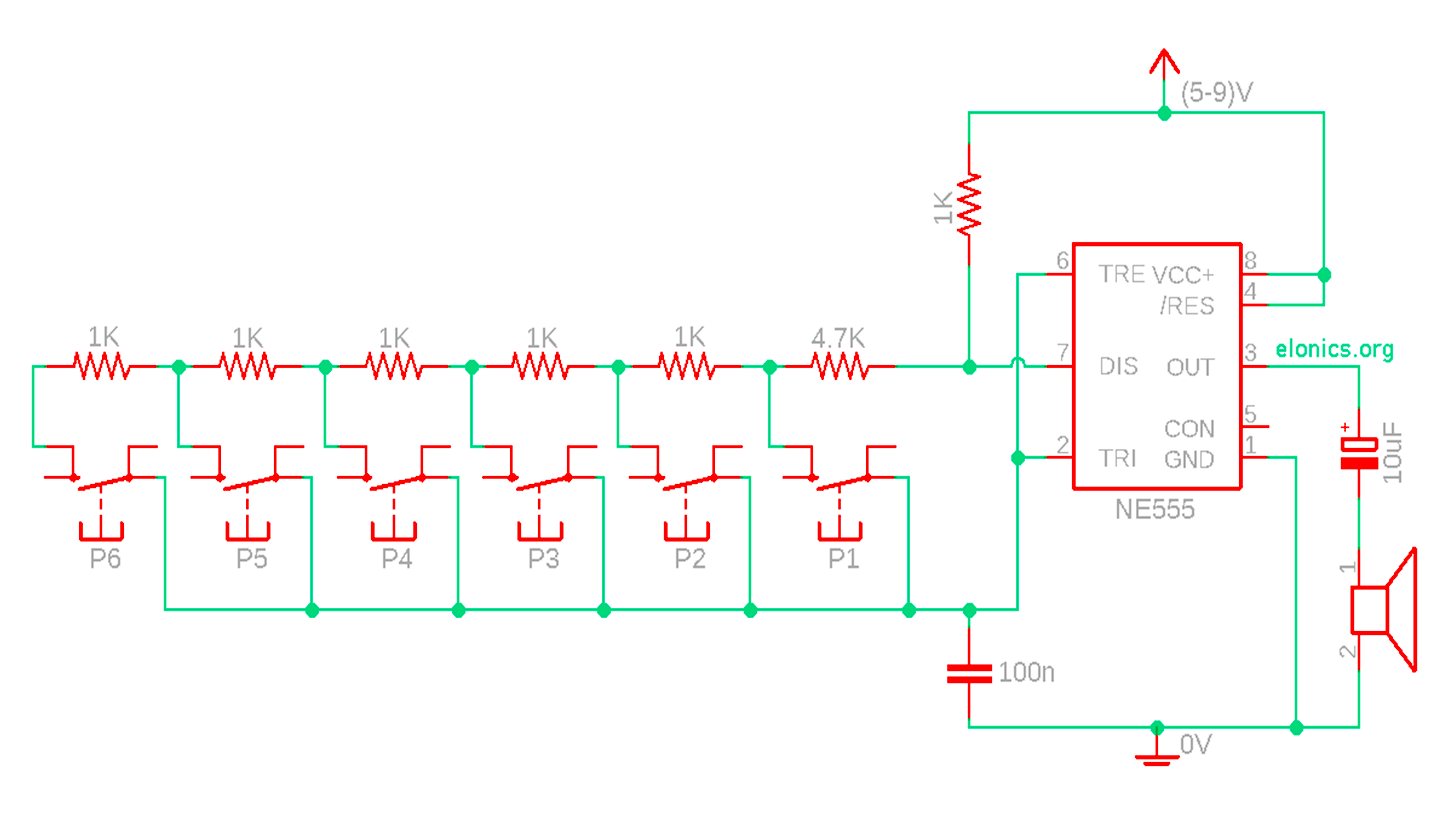
Did you know that you can make a simple piano using a 555 timer?
All you need is:
- 555 timer,
- Resistor assortment (390Ω, 620Ω, 910Ω,, 1.1kΩ 1.3kΩ, 1.5kΩ, 6.2kΩ),
- Two resistor assortment (1kΩ)
- 8 pushbuttons
- hookup wire 22 AWG
- 9V battery connector
- 9V battery
- Piezo buzzer and
- Capacitor 100 nF
- Solderless breadboard
After collecting the elements for your piano, the next step is to put it together. There are so many tutorials that you can find on Line. so do your research, find the best tutorial and start building. We promise it’s fun.
Solderless breadboards are designed to connect power from 9V batteries to their rows. Make sure the 555 timer chip’s pins straddle the empty channel running down the center of the breadboard before putting it on the right side of the breadboard.
Put even pressure on it until all of the pins are in their holes and the chip sits flat on the breadboard. The pins of the 555 are numbered 1, 2, 3, and 4 on the bottom from left to right and 5, 6, 7, and 8 on the top from right to left.
They run counter-clockwise starting at the lower left. You need to connect the capacitor between the 555’s pins 1 and 2.
Put a wire from pin 3 of the 555 to the positive pin of the breadboard, and connect it to the positive pin of the breadboard. Then press the piezo in place.
Now, let’s talk about the buttons. Start by putting a small hookup wire between pin 7 of the 555 and some columns to the left (see the orange wire in the picture above). Locate the 6.2kΩ resistor (blue-red-red) and connect it between the other end of this hookup wire and another column to the left.
After all the buttons and resistors are in the right place, connect the battery and start playing music.
Simple Fire Alarm
The fire alarm project is very simple to design and is a very important device to detect fire at the right time and prevent any damage.
The components for this device are
- the Piezo buzzer
- The fluorescent light starter
- PCB
- 9V BatterySnap
Start by removing the case of the fluorescent light starter and then remove the capacitor from it.
Connect the positive terminal of the buzzer with the positive terminal of the battery and the negative pin of the buzzer goes to one of the pins of the tube light starter. Another pin is connected to the negative pin of the battery and with that circuiting is completed.
In the circuit, the starter acts as the switch. When the bulb is heated, it acts closes the switch. When it cools, it acts as an open switch.
Digital School Bell With Timetable Display
As many things have been digitalized, the school bell remains the same old manual school bell, and since primary school has been a part of all our school activities.
So why not take the old-fashioned school bell into the future and design a digital school bell which does more than just ring?
We can design it to
- Display the name of the current and following class period
- Make a buzzer sound at the end of every class period
- Keep a timetable with Daily schedules
To develop this project you will need a controller STM32 with a Bluetooth module, LED display with buttons, basic electronics components, school bell buzzer, and PCB board.
It has a running mode and a settings mode. The settings mode allows the user to connect an android digital device, and when the running mode is on it serves as a digital school bell for the day.
The controller STM32 uses the display current and following class periods and allows the storage of the timetable and displays it to teachers and students and teachers.
Final thoughts
To know how the digital electronic world works, you don’t need to know algebra, complex formulas, or calculus. The only requirements are a desire to learn and an interest in digital electronics. We all know that we cannot imagine life without electronic devices because it has become a part of our life.
Learning the basic concepts of electronics is beneficial and essential as well. the world of electronics is divided into two main categories – Digitals electronics and power electronics. We hope we managed to impart some knowledge in electronics in this digital electronics projects ideas and inspire you to do them.