In this article, you will learn the site acceptance test (SAT) procedure of the PLC system and cabinet (Programmable Logic Controllers).
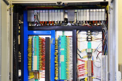
Once the PLC electrical panel has been dispatched from a manufacturer’s factory, it is then ready for installation at the industry site.
At the actual plant, the electrical panel is just not enough for the client to accept the machine. The overall working of the machine with actual process parameters will be considered for full acceptance.
The electrical panel is just a part of the system delivered; the whole machine is checked for proper performance. This test is called Site Acceptance Test (SAT).
PLC System Site Acceptance Test
The major difference between SAT and FAT is that an SAT is performed at the end-user / client-side and a FAT is performed at the manufacturer’s side.
Once the PLC system has reached the site, it is the job of the manufacturer to perform SAT with the client and handover it to them.
In this article, we will have a look at some of the basic general guidelines and steps that must be considered for performing an SAT.
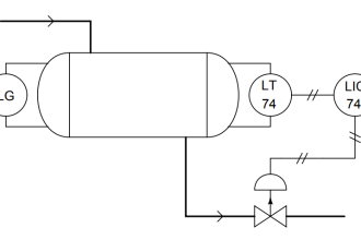
First ready all the necessary documents that are required for performing the SAT. It includes electrical drawings, mechanical drawings, P&ID layout, BOM (Bill of Materials), and other documents related to your system.
Now that the client is with you and ready for inspection; first of all, let them verify all the components and process parameters according to the documents visually. It is to be done to ensure that all the materials that you have sold to them are present in the system or not.
Let them verify the system and check whether the system that you have sent is designed according to it or not. So, as you must have read, this step is the visual verification of all the documents and electrical panels before powering them up.
Also, one more reason to visually verify is that sometimes, materials get damaged during transportation and logistics. So, it is necessary to check the system first before starting it.
Ensure that all the mechanical components, its fabrication, structure, its electrical field wiring is complete or not. This is to be done before powering up the electrical panel.
In short, ensure that the whole system is ready electrically, mechanically, and in a civil manner according to the P&ID layout.
Also, ensure that the piping is proper and there is no leakage from anywhere. It is also necessary to check that the utility like steam, water, etc. which you are getting from the client is proper or not.
After the visual inspection has been done, connect the main power supply to the panel and power it up.
Check the incoming voltage with a multimeter on its terminal board.
Check the voltage between earth to neutral and see if it is below 0.5V. If everything is proper, then turn on all the MCBs in the panel one by one.
Turning ON the MCBs and other circuit breakers means the panel is fully charged now. So, the PLC is also powered up eventually. Now that the PLC and HMI / SCADA are powered up, ensure that both are communicating properly.
Now, you have to check the IOs of the PLC. According to the wiring that you have done, check digital inputs first.
On giving the input at the desired terminal point in the panel or somewhere else, the corresponding PLC input must be turned on.
Then, check the digital outputs. According to the PLC output address that you have turned on, the physical PLC output must also turn on. When it is ON, check the device that you are turning on in the field. Then, check the analog inputs.
On giving the input, the corresponding PLC input must show analog counts accordingly. Then, check the analog outputs.
According to the PLC output address that you have given counts, the physical PLC output must also give the corresponding counts. Check the device where you are giving the counts.
One thing to remember before testing the IOs is that there are many interlocks sometimes for powering up a device accordingly. It has been designed according to process parameters and any lag or malfunction in it can hamper the performance.
So, it is necessary to test your IOs according to the process sequence that has been designed. This can avoid any untoward incident.
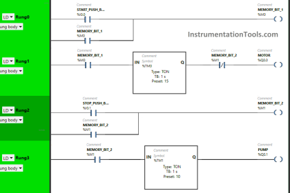
Run the whole system according to the logic that you have set in PLC and see if the system is working according to the designed process parameters or not.
As the actual process is running at the site, check the design working according to the environmental specifications with which it was made.
After the test has been performed and the system is running properly, you need to perform three tests with the client for handover –
- Installation Qualification (IQ),
- Operational Qualification (OQ) and
- Performance Qualification (PQ)
Installation Qualification (IQ) ensures that the machine is installed and placed properly according to design specifications.
Operational Qualification (OQ) ensures that the machine is operating properly according to the design specifications.
Performance Qualification (PQ) ensures that the final product that is impacted by the system is performing according to the client’s requirements and giving desired results or not.
After all this, SAT is completed and the system is now ready to run at the client-side.
In this way, we saw some general steps and guidelines in performing SAT for a PLC system.
If you liked this article, then please subscribe to our YouTube Channel for Instrumentation, Electrical, PLC, and SCADA video tutorials.
You can also follow us on Facebook and Twitter to receive daily updates.
Read Next: