Inst ToolsInst ToolsInst Tools
  • Ask
  • Courses
  • Videos
  • Q & A
    • Interview
      • Instrumentation
      • Electronics
      • Electrical
      • Practical Questions
    • MCQ
      • Instrumentation MCQ
      • Electrical MCQ
      • Electronics MCQ
      • Control Systems MCQ
      • Analog Electronics MCQ
      • Digital Electronics MCQ
      • Power Electronics MCQ
      • Microprocessor MCQ
      • Multiple Choice Questions
  • EE
    • Electronics
      • Electronics Q & A
      • Electronic Basics
      • Electronic Devices & Circuits
      • Electronics Animation
      • Digital Electronics
    • Electrical
      • Electrical Basics
      • Electrical Q & A
      • Power Electronics
      • Electrical Machines
      • Electrical Animation
      • Power Systems
      • Switchgear & Protection
      • Transmission & Distribution
  • Measure
    • Control Valves
    • Calibration
    • Temperature
    • Pressure
    • Flow
    • Level
    • Analyzers
    • Switches
    • Vibration
    • Solenoid Valve
  • Control
    • PLC Tutorials
    • Control Systems
    • Safety Instrumented System (SIS)
    • Communication
    • Fire & Gas System
  • More
    • Design
    • Tools
    • Animation
    • Basics
    • Formulas
    • Standards
    • TextBooks
    • Common
    • Software
    • Excel Tools
    • Erection & Commissioning
    • Process Fundamentals
    • Videos
    • Books
Search
All rights reserved. Reproduction in whole or in part without written permission is prohibited.
Reading: T Flip Flop PLC Ladder Diagram
Share
Notification Show More
Font ResizerAa
Inst ToolsInst Tools
Font ResizerAa
  • Courses
  • PLC Tutorials
  • Control Systems
Search
  • Ask
  • Courses
  • Videos
  • Q & A
    • Interview
    • MCQ
  • EE
    • Electronics
    • Electrical
  • Measure
    • Control Valves
    • Calibration
    • Temperature
    • Pressure
    • Flow
    • Level
    • Analyzers
    • Switches
    • Vibration
    • Solenoid Valve
  • Control
    • PLC Tutorials
    • Control Systems
    • Safety Instrumented System (SIS)
    • Communication
    • Fire & Gas System
  • More
    • Design
    • Tools
    • Animation
    • Basics
    • Formulas
    • Standards
    • TextBooks
    • Common
    • Software
    • Excel Tools
    • Erection & Commissioning
    • Process Fundamentals
    • Videos
    • Books
Follow US
All rights reserved. Reproduction in whole or in part without written permission is prohibited.
Inst Tools > Blog > PLC Tutorials > T Flip Flop PLC Ladder Diagram

T Flip Flop PLC Ladder Diagram

This is a PLC Program to implement T flip flop. Learn the ladder diagrams with example-based programming.

Last updated: November 3, 2023 12:27 pm
Editorial Staff
PLC Tutorials
3 Comments
Share
3 Min Read
SHARE

This is a PLC Program to implement T flip flop. Learn the ladder diagrams with example-based programming.

Contents
T Flip Flop Logic using PLCProblem DiagramProblem SolutionList of inputs & outputsList of inputsList of outputsM memoryPLC Ladder DiagramProgram DescriptionNetwork 1:Network 2:Network 3:Result

T Flip Flop Logic using PLC

Problem Description

Implement T flip flop in PLC using ladder diagram programming language.

Problem Diagram
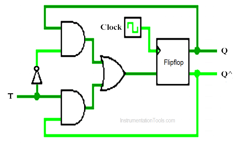
T Flip Flop Logic using PLC Ladder Diagram

Problem Solution

We will use PLC S7-1200 for this application. We can implement this logic by using other PLC also.

T flip flop has two inputs, one is clock input and other one is T (toggle) input.

Ladder diagram of the T flip flop can be obtained by using T input in this flip flop.

This can be done by rising edge instruction. But many PLC’s do not have such type of instruction. So for that PLCs we can use this logic.

List of inputs & outputs

List of inputs

  • T (Toggle) :- I0.0

List of outputs

  • output (Light) :- Q0.0
  • One Shot (OS) logic output :- Q0.1

M memory

  • Relay coil :- M0.0

PLC Ladder Diagram

For easy understanding, here we assumed ” a Light ” is connected at output to check the flipflop logic status.

T Flip Flop PLC
T flip-flop PLC Ladder
PLC Logic T flip flop

Program Description

For this application, we used S7-1200 PLC and TIA portal software for programming.

Network 1:

When T input (I0.0) is triggered, relay coil (M0.0) will go high immediately

Network 2:

During the second scan cycle, when Network 1 is scanned, status of Q0.1 is observed “1” .

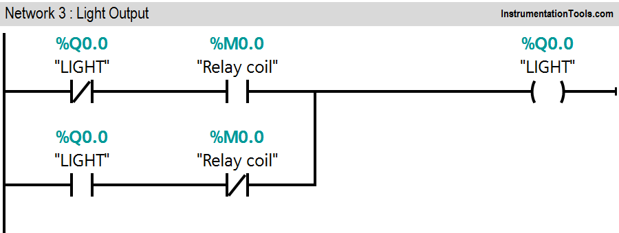
Network 3:

When the network 3 is scanned, it receives input “1” from the image table which was set while scanning network 1. It triggers light output (Q0.0).

Even if T input is withdrawn, the light output (Q0.0) does not change. Even if the T input is withdrawn, the light output (Q0.0) does not change.

This logic can be implemented by using OSR instruction or rising edge of the PLC. Here we used only latching concept to hold the output.

Note:- This example is only for explanation purpose only. We can implement this logic in other PLC also. This is the simple concept of T flip flop, we can use this concept in other examples also.

All parameters considered in example are for explanation purpose only, parameters may be different in actual applications. Also all interlocks are not considered in the application.

Result

T flipflop PLC ladder

Author: Bhavesh

If you liked this article, then please subscribe to our YouTube Channel for PLC and SCADA video tutorials.

You can also follow us on Facebook and Twitter to receive daily updates.

Read Next:

  • PLC Multiple Outputs Configuration
  • Latching Function using PLC
  • NC Contact For Stop Buttons
  • DCS Interview Questions
  • RSLogix 5000 PLC Programming
Don't Miss Our Updates
Be the first to get exclusive content straight to your email.
We promise not to spam you. You can unsubscribe at any time.
Invalid email address
You've successfully subscribed !
System Cabinet Health Checks – PLC and DCS Industrial Automation
Automatic Box Filling System using PLC Programming
Up Counter PLC Program
PLC Functional Block Diagram for Logic Gates
XG5000 PLC Programming for Automatic Exhaust Fan
Share This Article
Facebook Whatsapp Whatsapp LinkedIn Copy Link
Share
3 Comments
  • Archimedes says:
    September 9, 2018 at 8:14 pm

    thank you sir for all this helpfull articles! Just to inform you that i am still facing problems to download these tutorials to my PC even though i tried to use mozzilla as you told me earlier…Hope to find a solution to this problem. Thank you again!

    Reply
  • Jan Wieland says:
    March 12, 2021 at 7:26 pm

    In Network 1it should be %Q1.1 instead of %Q1.0.
    Otherwise it doesn´t work.

    Reply
  • Jan Wieland says:
    March 12, 2021 at 7:28 pm

    Oh, i meant %Q0.1 instead of %Q1.0, sorry

    Reply

Leave a Reply Cancel reply

Your email address will not be published. Required fields are marked *

Stay Connected

128.3kFollowersLike
69.1kFollowersFollow
208kSubscribersSubscribe
38kFollowersFollow

Categories

Recent Comments

  • Kamli on Top Free PLC Software
  • Guifty Shimica on Top Non-PLC Certification Courses for Automation Professionals
  • Guifty Shimica on Top Non-PLC Certification Courses for Automation Professionals
  • MIHARITSOA Aina Sitraka on Top Non-PLC Certification Courses for Automation Professionals

Related Articles

PLC Example on Manufacturing Line Assembly

PLC Example on Manufacturing Line Assembly

Free Download PLC Book

#10 PLC Best Practices – Assign Register Blocks by Function

Industrial Control Systems Security

Comparing ICS and IT Systems Security

How to Filter Digital and Analog Inputs in a PLC

How to Filter Digital and Analog Inputs in a PLC?

PLC Program for Solenoid, Pilot Lamp, and Switch with Alarm

PLC Program for Solenoid, Pilot Lamp, and Switch with Alarm

Single Line Diagram of UPS System

UPS Selection Factors for a Control System

Sorting and Counting Products on Conveyors by Color

PLC Programming for Multi-Color Sorting Conveyor System

Introduction to Schneider PLC

Different Types of Schneider PLC

More Articles

Blowdown Valve (BDV) and Shutdown Valve (SDV)

Difference between Blowdown Valve (BDV) and Shutdown Valve (SDV) ?

Electrical Machines Questions and Answers

DC Machines Torque Quiz

Pneumatic valve operation in sequence mode

Sequential PLC Programming for the Pneumatic Valves

grounded thermocouple junction

Types of Thermocouple Measuring Junction

The Hardware Structure of DCS

DCS Applications and Hardware Structure of Plant Automation

PLC Program for Fishpond Water Level Monitoring System

PLC Program for Artificial Fishpond Water Level Monitoring System

Ion Analyzers Questions and Answers

Ion Selective Electrodes Questions and Answers

Totally Enclosed Fan Cooled (TEFC) Motor

Totally Enclosed Fan Cooled (TEFC) Motors Rampant Winding Burnouts

Follow US
All rights reserved. Reproduction in whole or in part without written permission is prohibited.
Welcome Back!

Sign in to your account

Username or Email Address
Password

Lost your password?