Inst ToolsInst ToolsInst Tools
  • Courses
  • Automation
    • PLC
    • Control System
    • Safety System
    • Communication
    • Fire & Gas System
  • Instrumentation
    • Design
    • Pressure
    • Temperature
    • Flow
    • Level
    • Vibration
    • Analyzer
    • Control Valve
    • Switch
    • Calibration
    • Erection & Commissioning
  • Interview
    • Instrumentation
    • Electrical
    • Electronics
    • Practical
  • Q&A
    • Instrumentation
    • Control System
    • Electrical
    • Electronics
    • Analog Electronics
    • Digital Electronics
    • Power Electronics
    • Microprocessor
  • Request
Search
  • Books
  • Software
  • Projects
  • Process
  • Tools
  • Basics
  • Formula
  • Power Plant
  • Root Cause Analysis
  • Electrical Basics
  • Animation
  • Standards
  • 4-20 mA Course
  • Siemens PLC Course
Reading: PLC Program to Heat and Bend Glass Tubes
Share
Notification Show More
Font ResizerAa
Inst ToolsInst Tools
Font ResizerAa
  • Courses
  • Design
  • PLC
  • Interview
  • Control System
Search
  • Courses
  • Automation
    • PLC
    • Control System
    • Safety System
    • Communication
    • Fire & Gas System
  • Instrumentation
    • Design
    • Pressure
    • Temperature
    • Flow
    • Level
    • Vibration
    • Analyzer
    • Control Valve
    • Switch
    • Calibration
    • Erection & Commissioning
  • Interview
    • Instrumentation
    • Electrical
    • Electronics
    • Practical
  • Q&A
    • Instrumentation
    • Control System
    • Electrical
    • Electronics
    • Analog Electronics
    • Digital Electronics
    • Power Electronics
    • Microprocessor
  • Request
Follow US
All rights reserved. Reproduction in whole or in part without written permission is prohibited.
Inst Tools > Blog > PLC Tutorials > PLC Program to Heat and Bend Glass Tubes

PLC Program to Heat and Bend Glass Tubes

PLC Program to Heat and Bend Glass Tubes : Glass industry, heated glass tubes are passing in a process line having a particular length which are to be bent.

Last updated: November 3, 2023 2:46 pm
Editorial Staff
PLC Tutorials
1 Comment
Share
4 Min Read
SHARE

This is a PLC Program for heating and bending glass tubes.

Contents
Heat and Bend Glass TubesProblem DiagramProblem SolutionList of Inputs and OutputsPLC Ladder Logic to heat and bend glass tubesLogic Description

Heat and Bend Glass Tubes

Problem Description

  • In glass industry heated glass tubes are passing in a process line having a particular length which are to be bent.
  • We need to bend glass tube in U-shape. These bended glass tube is used for fluorescent bulbs.
  • Implement this process in PLC using ladder diagram programming language.

Problem Diagram
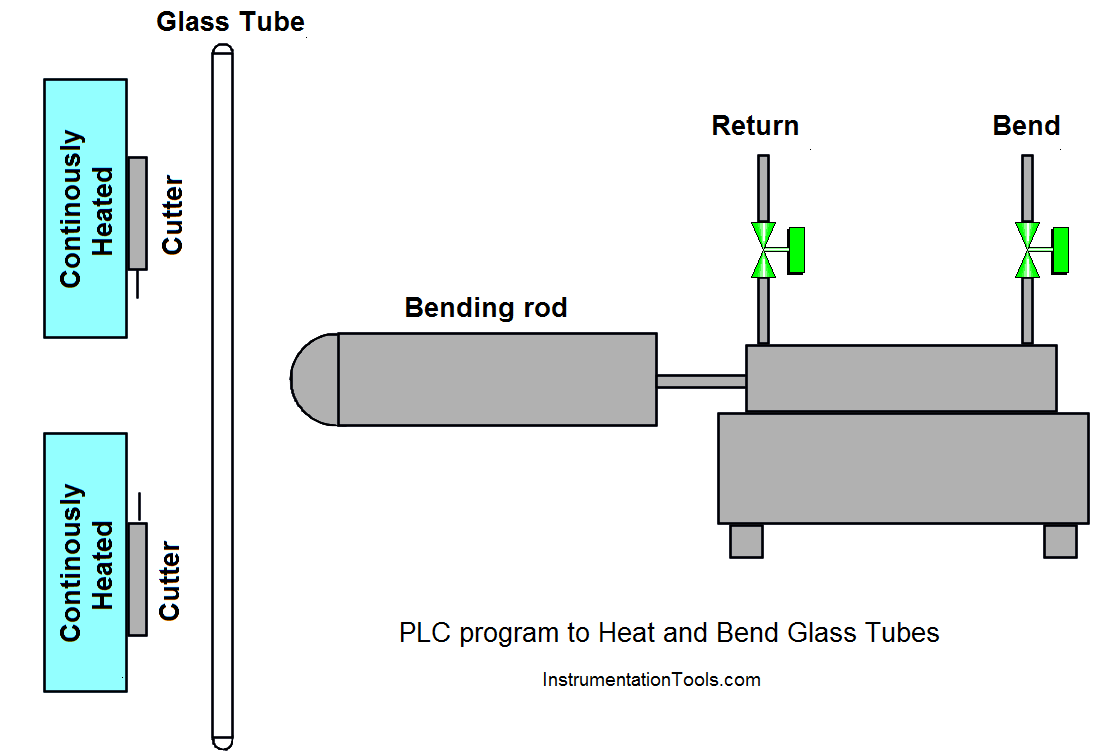
PLC Program to Heat and Bend Glass Tubes

Problem Solution

For this process, we will consider two pneumatic rods that force the glass tube through metal support for the bending process.

During this process metal support is continuously heated so that glass does not break while bending.

When the bending process is completed, two cutters are used to cut the bent glass.

Proximity switch detects the length to be cut by the cutter in the cutting process.

Metal supports are mounted close to each other so the bending rod and glass tube can pass through it.

List of Inputs and Outputs

Inputs List 

  • START PB :- I0.0
  • STOP PB :- I0.2
  • Glass detector :- I0.3
  • Glass length detector (proximity) :- I0.6

Outputs List 

  • Bend valve :- Q0.0
  • Cutter :- Q0.2
  • Return valve :- Q0.3

M memory 

  • Master coil :- M0.0
  • Relay coil 1:- M0.1

PLC Ladder Logic to heat and bend glass tubes
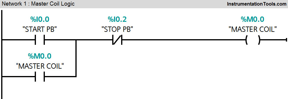
PLC Ladder Logic heat and bend glass tubes
PLC Glass Tube
PLC Heat Bend Glass
PLC Bend Glass
PLC Heat Glass
Heat and Bend Glass Tube

Logic Description

For this application we used S7-300 PLC and TIA portal software for programming.

Network 1:

Master coil will be ON (M0.0) when START PB (I0.0) will be pressed and master coil can be stopped by pressing STOP PB (I0.2).

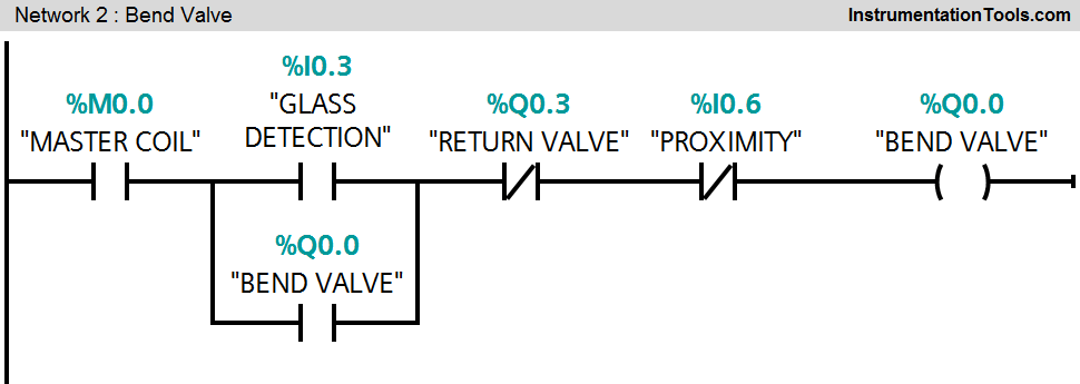
Network 2:

When glass detector sensor (I0.3) detects the glass, bending process will be ON or bend vale (Q0.0) will be ON.

Network 3:

When glass length sensor is detected (I0.6), relay coil 1(M0.1) will be ON for next command.

Network 4:

If relay coil 1(M0.1) is ON, cutter (Q0.2) will be ON

Network 5:

Timer will start to count time when relay coil 1 (M0.1) is ON after 20sec delay (here we assumed time for cutting) cutter (Q0.2) will turn OFF.

Network 6:

When cutter output is ON (Q0.2) and bend valve (Q0.0) is OFF, return valve (Q0.3) will be ON.

Note :- Above application may be different from actual application. This example is only for explanation purpose only. We can implement this logic in other PLC also. This is the simple concept of heating and bending of glass tube in industry, we can use this concept in other examples also.

All parameters considered in example are for explanation purpose only, parameters may be different in actual applications. Also all interlocks are not considered in the application.

Author: Bhavesh

If you liked this article, then please subscribe to our YouTube Channel for PLC and SCADA video tutorials.

You can also follow us on Facebook and Twitter to receive daily updates.

Read Next:

  • Latching & unlatching Circuit
  • PLC Tank Heating Control using Heater
  • Controlling Sequence of Conveyors
  • PLC Automatic Heating and Mixing of Products
  • Food Processing Industry PLC Example
Don't Miss Our Updates
Be the first to get exclusive content straight to your email.
We promise not to spam you. You can unsubscribe at any time.
Invalid email address
You've successfully subscribed !

Continue Reading

PLC Instruction List for Motor Reverse and Forward Direction
Process Interlocks and Trips
Programmable Logic Controller Practice Tests
How to Use Encode and Decode Instructions in PLC ?
Various Communication Protocols in PLC
Moving Data between PLCs – Siemens Basics – TSEND TRCV
Share This Article
Facebook Whatsapp Whatsapp LinkedIn Copy Link
Share
1 Comment
  • Gnana Moorthy says:
    October 28, 2018 at 7:01 pm

    I/O addressing mismatching as per you description and ladder diagram . Please correct it.

    Reply

Leave a Reply Cancel reply

Your email address will not be published. Required fields are marked *

Stay Connected

128.3kFollowersLike
69.1kFollowersFollow
210kSubscribersSubscribe
38kFollowersFollow

Categories

Explore More

Control Two Motors in Sequence after Time Delay – Circuit, Operation
PLC Program to Drain Same Products from Two Tanks
Introduction to PLC Ladder Diagrams
How to Communicate with Excel from RsLinx?
PLC Basics – Manual Control, Closed Loop, ON-OFF with Hysteresis
Laws of Boolean Algebra using Ladder Logic
Implement UDT in PLC Programming: User-Defined Data Type
UPS Working Principle and Types – Offline and Online UPS Systems

Keep Learning

PLC Programming Basics for a Packing Machine Control System

PLC Packing Machine Control System Program in XG5000

Different PLC available in the Simatic S7 generation

Overview of SIEMENS PLC – S7-1500, S7-1200, S7-400, S7-300

PLC FBD Example for Tank Liquid Heating Control by Steam Flow

PLC FBD Example for Tank Liquid Heating Control by Steam Flow

Masked Move Instructions

How to use Masked Move Instruction in PLC

Allen Bradley PLC Emulator

How to Work with Allen Bradley RsLogix Emulator?

Converter Instruction in Siemens PLC Programming

Converter Instruction in Siemens PLC Programming

Opposite Acting Control Valves Application

PLC Ladder Logic for Opposite Acting Control Valves Application

Complementary Split Range Control

What is Complementary Split Range Control (CSRC)?

Learn More

Comparison of Accuracy and Precision

Difference between Accuracy and Precision

Paint Mixing System

Paint Mixing System

Metal tube Variable Area Flowmeters Principle

Metal Tube Variable Area Flow Meters Principle

PLC Temperature Control using Pulse Width Modulation

PLC Temperature Control using Pulse Width Modulation (PWM)

Overview of Proximity Switches

Digital Electronics Multiple Choice Questions

Liquid Crystal Display Objective Questions

Parallel RLC Circuit

Impedance in RLC Circuits

Calculate Hydraulic System Fluid Pressure

Calculate Hydraulic System Fluid Pressure

Menu

  • About
  • Privacy Policy
  • Copyright

Quick Links

  • Learn PLC
  • Helping Hand
  • Part Time Job

YouTube Subscribe

Follow US
All rights reserved. Reproduction in whole or in part without written permission is prohibited.
Welcome Back!

Sign in to your account

Username or Email Address
Password

Lost your password?