Testing Procedure for Fiber Optic Cable Drums
- One end of the cable drum will be prepared by using the proper tools.
- Take the prepared end of the cable inside the splice van to maintain the temperature and dust-free environment
- Make the OTDR (Optical Time-domain Reflectometer) ready for testing. When the OTDR is ready, strip the fiber and cleave it by means of a diamond-edged cleaver to ensure the cleaving end should be perpendicular.
- Connect the fiber to the OTDR by making a mechanical joint. The mechanical joint will be done by using two connectors coupled to each other through a mechanical coupler.
- Now the fiber is ready for testing. Keep the OTDR in average mode and shoot the laser through the fiber for 10 seconds.
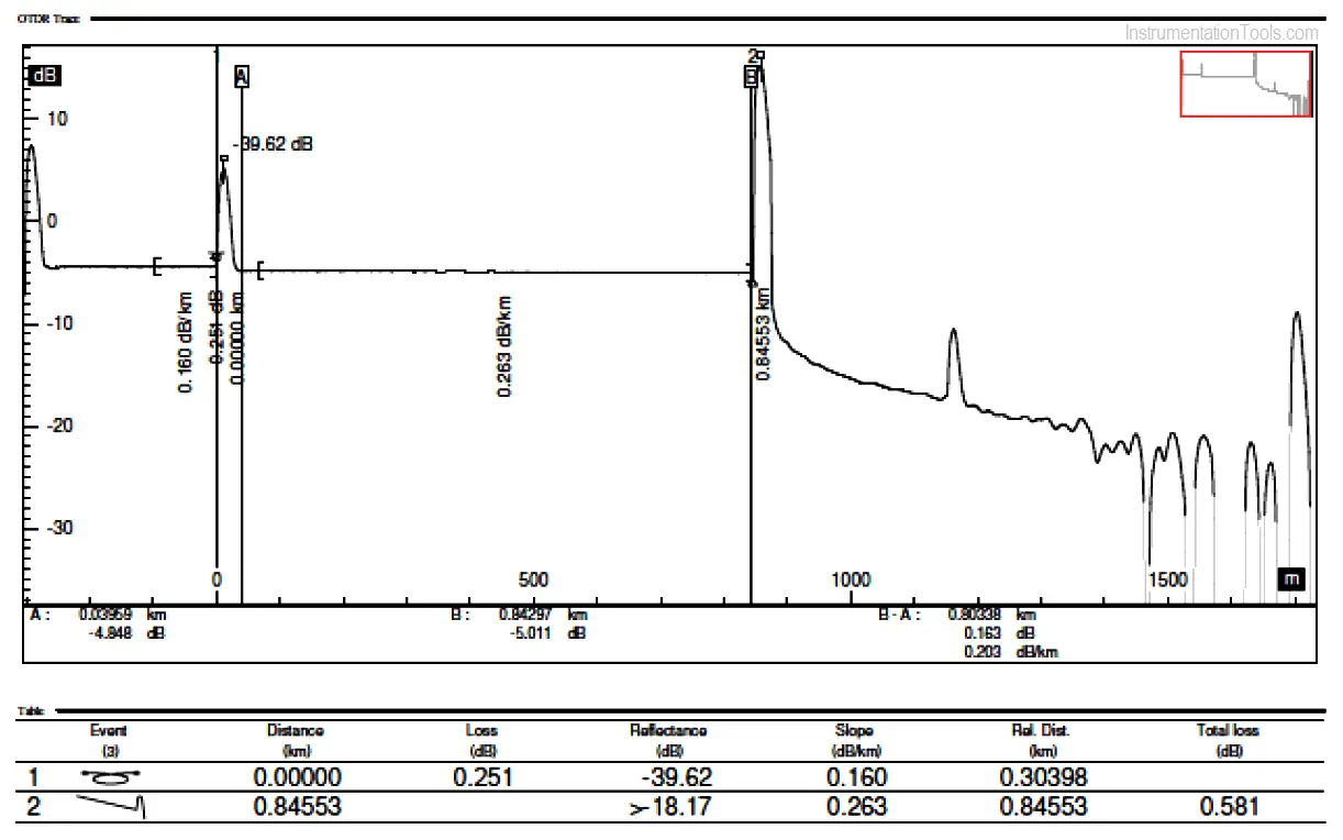
- When the laser will be off, put the cursor “B” at the end of the cable and Cursor “A” around 80 meters from starting (This 80meters is called Dead Zone, because of the changing in the medium of the laser frequency in a very short distance).
- Now note the dB/Km loss of the cable.
a. 1310nm <= 0.4 dB/Km
Contents
b. 1550nm <= 0.25dB/Km
If the loss is more than the above-mentioned parameter checks the mechanical splice or cleave the fiber again and follow the above procedures again.
- If still, the problem persists then there is some problem with the fiber.
- Then proceed with the same procedure for all the fibers individually.
- All the readings should be witnessed and checked.
Below equipment shall be used to perform the OTDR testing
Test Equipment type:
- Optical Power Meter
The above procedure is for the fiber optic cable drum testing, upon successful completion of the testing next step is for the installation, inspection, and testing of the fiber optic cable.
General Checks
- Check the correctness of cable code & size.
- Cable identity and tag number shall be checked.
- Proper gland installation.
- Cable bending radius shall be checked
- Cabinet and/or Joint Box Cover Seals undamaged and Unused Cable Entries plugged correctly.
OTDR & Continuity Tests
- OTDR checked before laying of the cable.
- Fiber OTDR (for UG Cables) & continuity checked after laying the cable.
- OTDR and point to point continuity check after termination.
- Final OTDR test results.
Sample report as a reference:
Termination Checks
Field Device to Patch Panel
- Fibers terminated correctly at the device.
- Fibers terminated correctly at patch Panel.
- Gland earth tab connected to the patch panel.
- Fiber identification correct.
Patch Panel to Patch Panel / Control Panel
- Fiber terminated correctly at the patch panel.
- Fiber cores terminated correctly at the patch Panel/control panel.
- Gland earth tab connected to earth panel.
- Fiber identification in patch panel/control panel correct.
Author: Mohammed Khaleel
Read Next:
- Fiber Optic Cable Splicing
- Communication Networks
- History of OPC Protocol
- DNP3 Communication Protocol
- Industrial Automation Security