PLC program for trash compactor to compress the trash and then it should throw the trash out of it.
Note: This simple PLC logics mainly focuses on engineering students to practice the programming.
Trash Compactor
Problem Statement:
Design a PLC ladder logic for the following application.
We are using one toggle switch and one sensor to control the compression and throw actuator.
When a Start Button is pressed, the compactor should compress trash for 20 seconds and then it should throw the trash out of it for 10 seconds. While throwing the trash out, there should be presence of Trash Collector tray.
PLC Basics
Instrumentation Tools provides the PLC basics training videos for the students and engineers.
This video explains the trash compactor programming.
Inputs and Outputs
Digital Inputs:
Start Button: I0.0
Tray Sensor: I0.1
Digital Outputs:
Compression: Q0.0
Throw Actuator: Q0.1
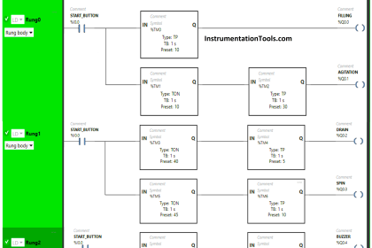
PLC Program
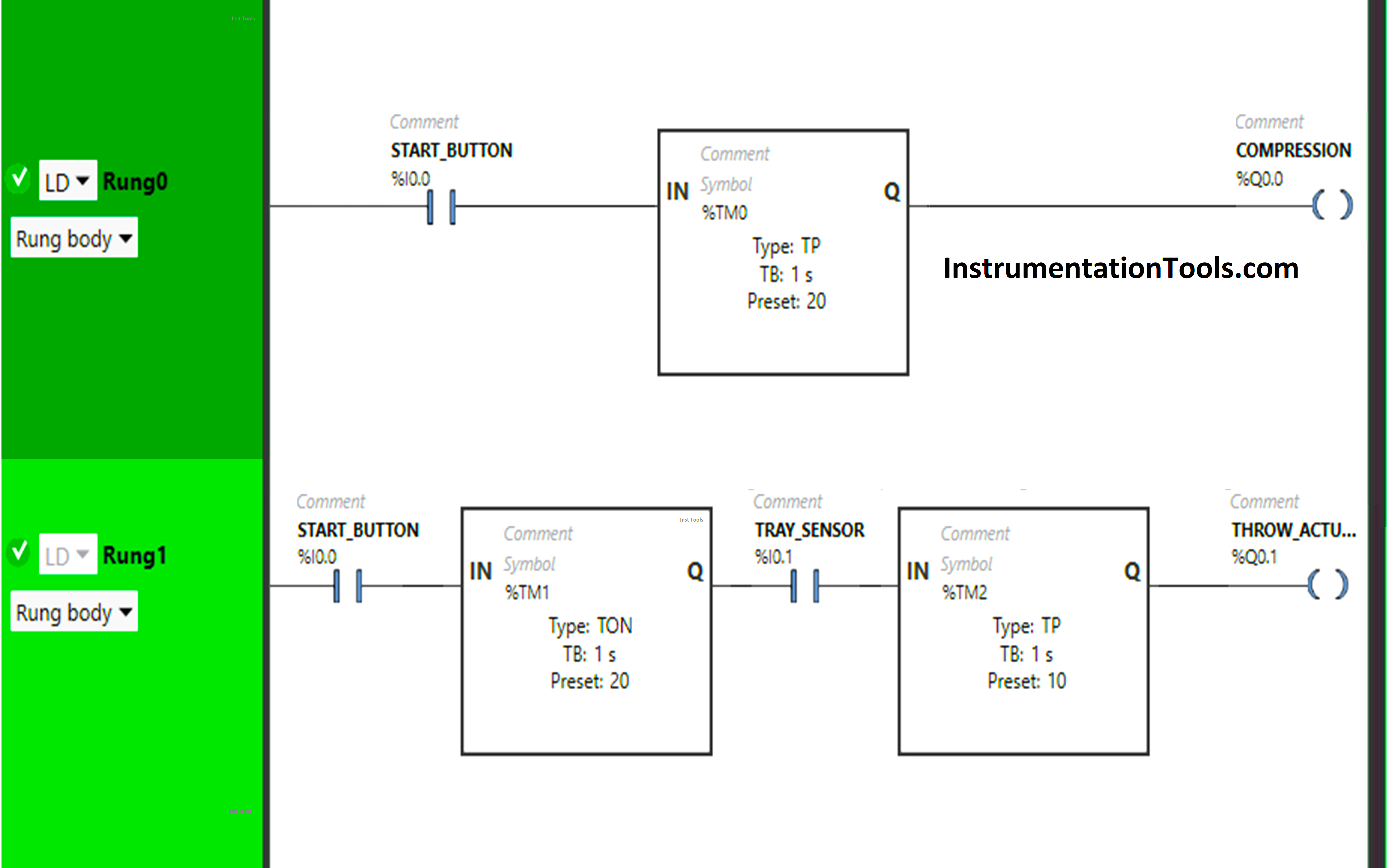
Explanation
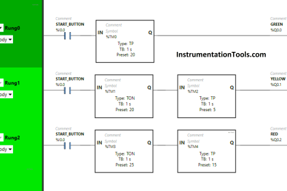
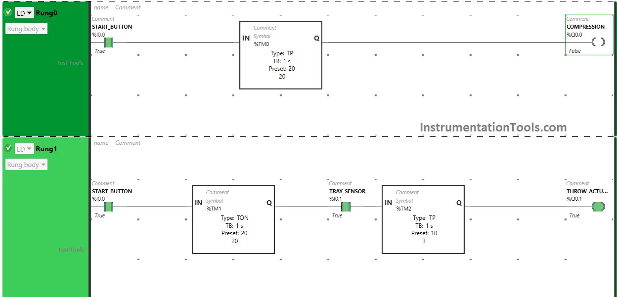
We have used Normally Open Contacts for the Start Button (I0.0) and Tray sensor (I0.1).
In Rung 0:
- Normally Open Contact is used for the Start Button (I0.0) to Turn ON the output Compression (Q0.0).
- Timer-type TP is used to Turn ON the output Compression (Q0.0) for a limited time.
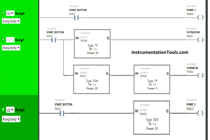
In Rung 1:
- Normally Open Contact is used for the Start Button (I0.0) to Turn ON the output throw (activates) the actuator (Q0.1).
- Timer-type TON is used to delay the turning ON time of the output throw (activates) the actuator (Q0.1) for some time.
- Normally Open Contact is used for Tray Sensor (I0.1) to Turn ON the output throw actuator (Q0.1).
- Timer-type TP is used to Turn ON the output Throw Actuator (Q0.1) for a limited time.
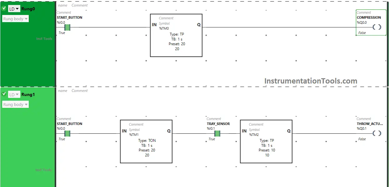
PLC Simulation – when the Start Button is turned ON
When the Start Button (I0.0) is turned ON, the output Compression (Q0.0) will turn ON or (Compactor compresses Trash) as Normally Open Contact used for Start Button (I0.0) will be in True State.
This allows the signal to pass through it and turns ON the output Compression (Q0.0) for 20 seconds as Timer Function Block type TP is used to Turn ON the output Compression (Q0.0) for a limited time. The time is set to 20 seconds.
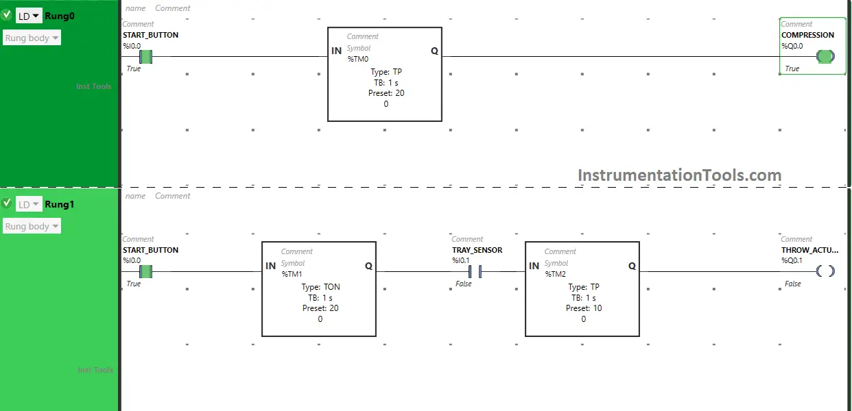
After 20 seconds, the output Compression (Q0.0) will turn OFF.
Also, when the Start Button (I0.0) is turned ON in Rung1, the output Throw Actuator (Q0.1) will turn ON after 20 seconds, (i.e immediately when the output compression (Q0.0) turns OFF) as Timer Function Block TON is used to delay the turning ON time of the output Throw Actuator (Q0.1). The time is set to 15 seconds.
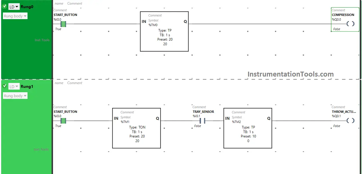
After 15 seconds, the Throw Actuator (Q0.1) will turn ON or ( Compactor throws the trash out).
The output Throw Actuator (Q0.1) will turn ON only when Tray Sensor (I0.1) gets activated or (Sensor detects Tray) because Normally Open Contact used for Tray Senor (I0.1) will be in True State and allows the signal to pass through it and turns ON the output Throw Actuator (Q0.1).
The output Throw Actuator turns ON only for 10 seconds as Timer Function Block type TP is used to Turn ON the output Throw Actuator (Q0.1) for a limited time.
The time is set to 10 seconds. After 10 seconds, the output Throw Actuator (Q0.1) will turn OFF.
If you liked this article, please subscribe to our YouTube Channel for PLC and SCADA video tutorials.
You can also follow us on Facebook and Twitter to receive daily updates.
Read Next:
- PLC Example Switch Program with Timers
- PLC Program for Two-Way Switch Logic
- PLC Programming using Limit Switch
- Automated Garage Gate PLC Control
- Pumping and Draining Ladder Logic