In this article, you will learn the PLC program for solenoid, pilot lamp, and switch with alarm for industrial control applications.
Disclaimer: The PLC program showcased here is for educational purposes only which is for students and technicians to learn foundational concepts of PLC.
PLC Program for Solenoid
Problem Statement
Design a PLC ladder logic for the following application.
We are using one push button to control the Solenoid, Pilot Lamp, and Alarm.
When the Push Button is pressed and then released, then the Solenoid and the Pilot Lamp will be ON.
When the Push Button is pressed again and then released, then the Solenoid and the Pilot Lamp will be OFF and the Alarm will be ON.
Essential PLC Lessons
These PLC video lessons are helpful in learning the basics of PLC programming.
Inputs and Outputs
Digital Inputs:
The digital inputs listed here.
Push Button 1: I0.0
Digital Outputs:
The digital outputs listed here.
Solenoid: Q0.0
Pilot Lamp: Q0.1
Alarm: Q0.2
Ladder Logic for Solenoid, Pilot Lamp, Switch
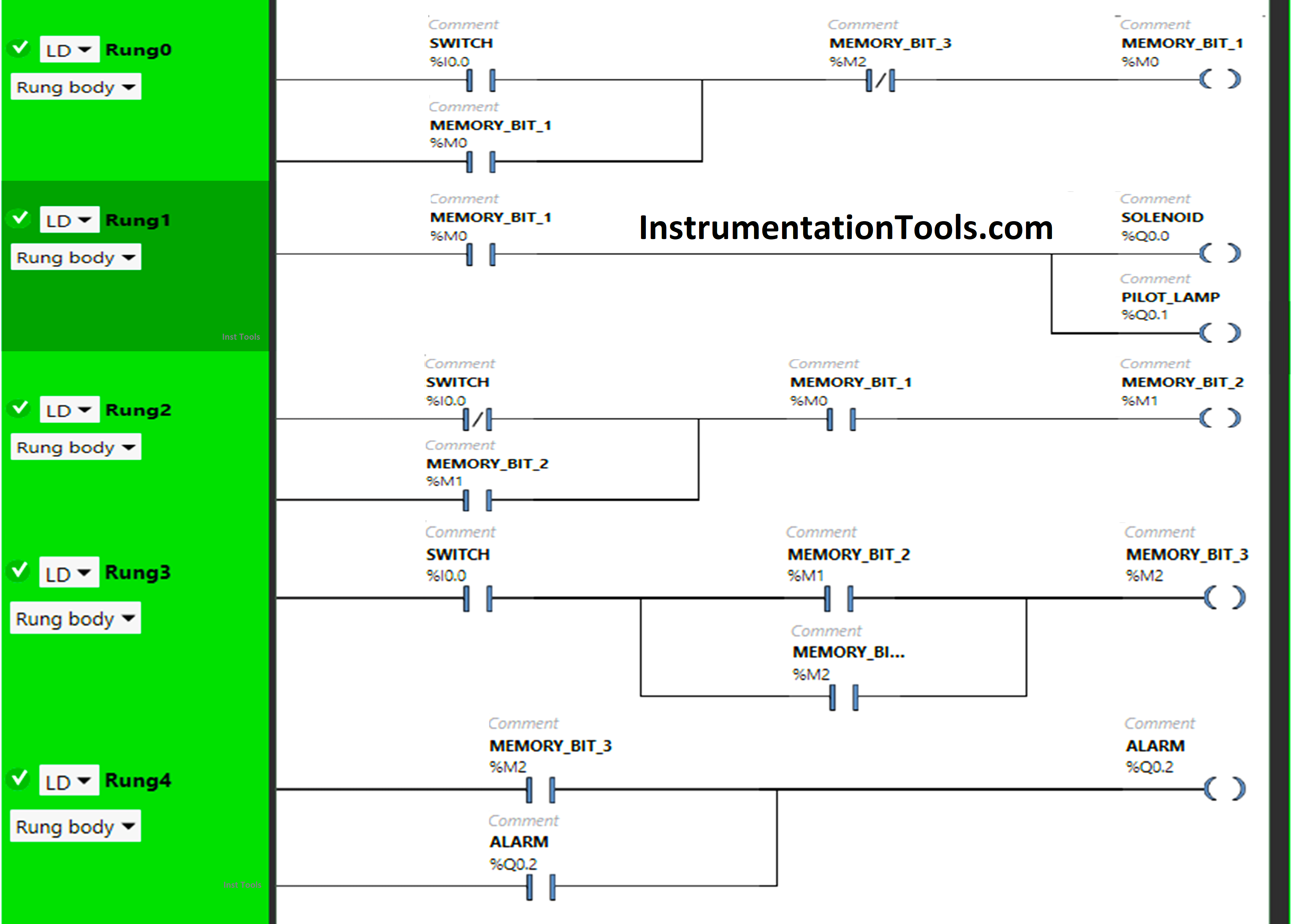
PLC Program Explained
In this PLC program, we have used Normally-Open Contacts as well as Normally-Closed Contacts and Memory Bits.
Normally Closed Contact is used for Push Button in Rung 2 and for Memory Bit 3 in Rung 0.
In Rung 0:
1) Normally Open Contact is used for Push Button to turn ON the Memory Bit 1.
2) Normally Closed Contact is used for Memory Bit 3 to OFF the Memory Bit 1.
3) Latching is used for Memory Bit 1 so that when the Push Button is turned OFF, Memory Bit 1 still remains ON.
In Rung 1:
1) Normally Open Contact is used for Memory Bit 1 to turn ON the Solenoid and Pilot Lamp.
In Rung 2:
1) Normally Closed Contact is used for Push Button and Normally Open Contact is used for Memory Bit 1 to turn ON Memory Bit 2.
2) As Memory Bit stores the data, Memory Bit 2 is used to store the data that Push Button has been released.
3) Latching is used for Memory Bit 2 so that when the Normally Closed Contact used for the Push Button is in a True state, Memory Bit 2 still remains ON.
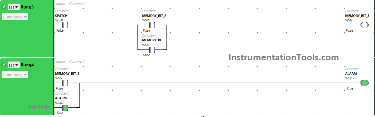
In Rung 3:
1) Normally Open Contact is used for Push Button to turn ON the Memory Bit 3.
2) Memory Bit 2 is used to store the data when the Push Button is pressed again.
3) Memory Bit 3 i.e. latched with Memory Bit 2 is used to turn OFF Memory Bit 1, So that when Memory Bit 3 is turned ON in Rung 3, Normally Closed Contact is used for Memory Bit 3 in Rung0 will be in True state and Memory Bit 1 will turn OFF. Then, In Rung1, Normally Open Contact used for Memory Bit 1 will not pass as it is in a false state And the Solenoid and Pilot Lamp will Turn OFF.
In Rung 4:
1) Normally Open Contact is used for Memory Bit 3 to turn ON Alarm.
2) Latching is used for the Alarm so that when Memory Bit 3 turns OFF, the Alarm still remains ON.
So, When the Push Button is pressed, the signal will pass through the Push Button as Normally Open Contact used for the Push Button is in the True state. In a false state, Normally Closed Contact used for Memory Bit 3 will also pass the signal, and Memory Bit 1 will Turn ON and it will store the data that the Push Button has been Pressed.
In Rung1, the Solenoid and Pilot Lamp will Turn ON as Normally Open Contact used for the Memory Bit is in a True state. When the Push Button is released, Memory Bit 1 in Rung0 still remains ON because Latching is used for Memory Bit 1 in Rung0. Also, the Solenoid and Pilot Lamp remain ON as Memory Bit 1 is still ON.
In Rung2, Memory Bit 2 will Turn ON as the Normally Closed Contact used for the Push Button is in a false state, and the Normally Open Contact used for Memory Bit 1 is in a True state. Memory Bit 2 will store the data that the Push Button has been released. When the Push Button is pressed again, it will Turn ON Memory Bit 3 in Rung0, Rung3, and Rung4 then the Solenoid and Pilot lamp will Turn OFF because Memory Bit 3 in Rung0 will not pass the signal to Memory Bit 1 as Normally Closed Contact used for it is in True state and Memory Bit 1 will Turn OFF.
In Rung1, Normally Open Contact used for Memory Bit 1 is in a false state and will not pass the signal to the Solenoid and Pilot Lamp. In Rung4, the Alarm will Turn ON. When the Push Button is released, the Alarm still remains ON as Latching is used for the Alarm in Rung4.
PLC Simulation Findings
Now we simulate our PLC program and show the results below. In some cases, we may show only the required part of the logic instead of complete code.
When Push Button 1 is PRESSED
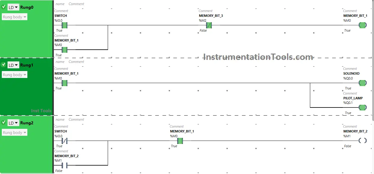
In Rung0, the signal will pass through the Push Button as Normally Open Contact used for the Push Button is in a True state.
In a false state, Normally Closed Contact used for Memory Bit 3 will also pass the signal, and Memory Bit 1 will Turn ON and it will store the data that the Push Button has been Pressed.
In Rung1, the Solenoid and Pilot Lamp will Turn ON as Normally Open Contact used for the Memory Bit is in a True state.
When Push Button is RELEASED
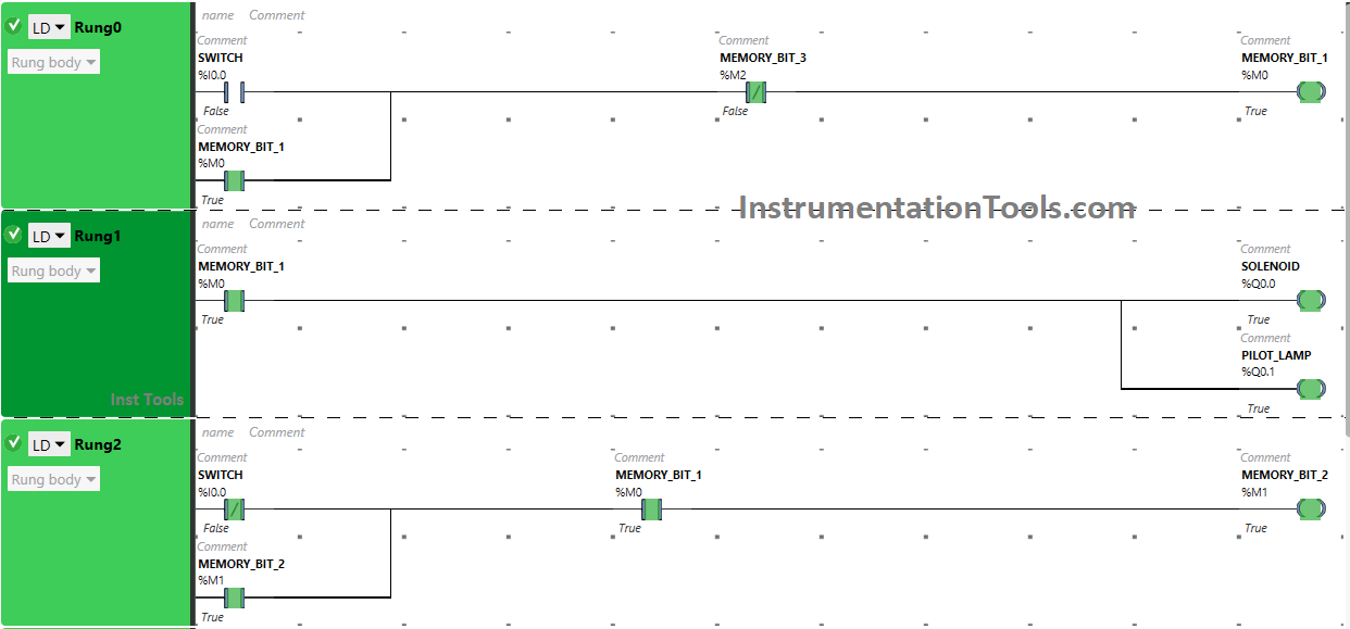
When the Push Button is released, Memory Bit 1 in Rung0 still remains ON because Latching is used for Memory Bit 1 in Rung0.
Also, the Solenoid and Pilot Lamp remain ON as Memory Bit 1 is still ON.
In Rung2, Memory Bit 2 will Turn ON as the Normally Closed Contact used for the Push Button is in a false state, and the Normally Open Contact used for Memory Bit 1 is in a True state. Memory Bit 2 will store the data that the Push Button has been released.
When Push Button is PRESSED Again (Second Press)
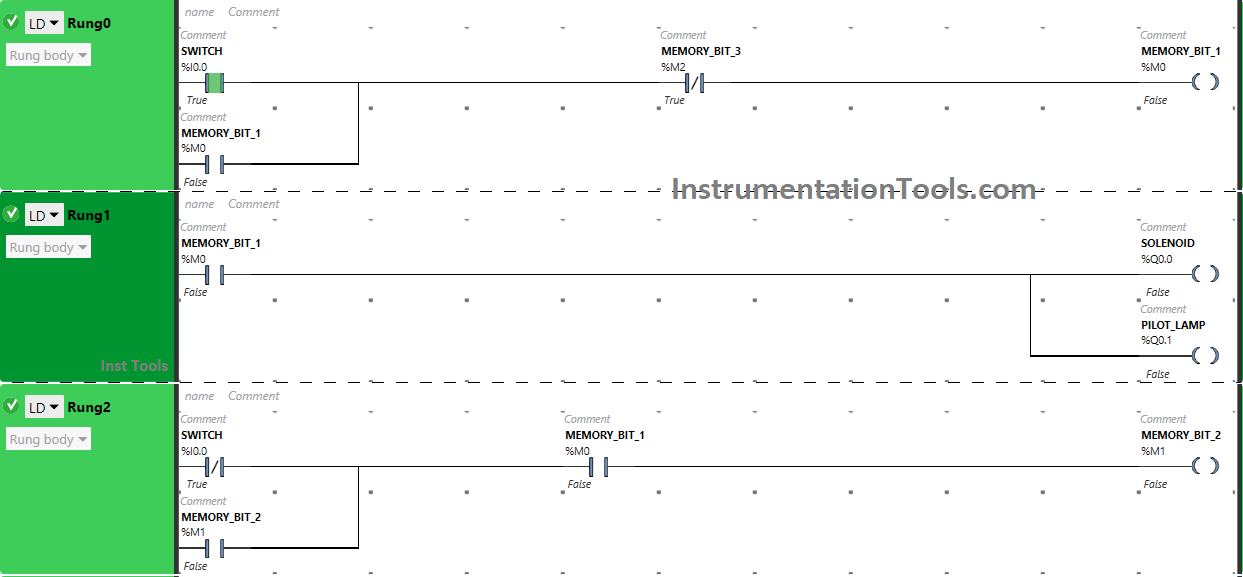
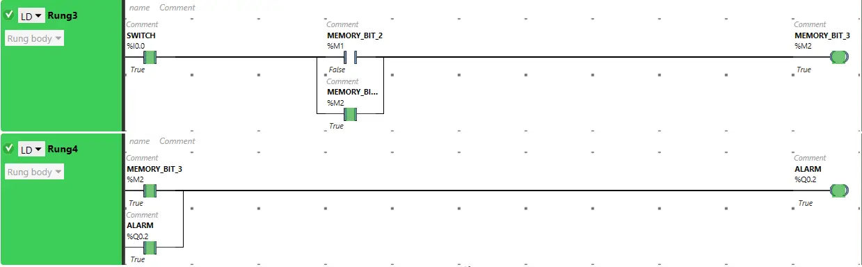
Pressing the Push Button again will Turn ON Memory Bit 3 in Rung0, Rung3, and Rung4 then the Solenoid and Pilot lamp will Turn OFF because Memory Bit 3 in Rung0 will not pass the signal to Memory Bit 1 as Normally Closed Contact used for it is in True state and Memory Bit 1 will Turn OFF.
In Rung1, Normally Open Contact used for Memory Bit 1 is in a false state and will not pass the signal to the Solenoid and Pilot Lamp. In Rung4, the Alarm will Turn ON.
When Push Button is RELEASED Again (Second Release)
When the Push Button is released, the Alarm still remains ON as Latching is used for the Alarm in Rung4.
If you liked this article, please subscribe to our YouTube Channel for PLC and SCADA video tutorials.
You can also follow us on Facebook and Twitter to receive daily updates.
Read Next:
- PLC Push Button to Turn ON OFF Output
- PLC Instructions TON, TOF, TP and TONR
- Automatic Motor START and STOP Circuit
- PLC Motor Logic with START Pushbuttons
- What is a Pilot Valve? When do we use it?