The use of Open Standard communications for Supervisory Control and Data Acquisition (SCADA) is well established in an increasing number of utility and industry sectors across the globe. This has provided significant benefits in system deployment and operation.
DNP3 is one of the most successful SCADA open standards adopted across the globe. In particular the Water Sector have adopted DNP3 for SCADA communications on a wide scale basis. Use of DNP3 in the Gas and Oil sectors has also been gaining ground.
Concept of DNP3
DNP3 is a commonly misunderstood term that you may have heard referred to when talking about SCADA and telemetry systems.
We have included some information here to try to demystify DNP3 for those who are not as technically savvy with telemetry systems. DNP stands for Distributed Network Protocol.
Firstly, we are going to use the analogy of two humans communicating in order to help understand where DNP3 fits.
When we communicate between each other we may use a great variety of different communications mediums such as a walkie talkie or 2 way radio, a fixed telephone line, a mobile telephone line or perhaps over the internet using skype or similar. While the medium we use can change, it will be necessary for us to communicate using the same language, i.e. English.
When we talk about communicating around our SCADA and telemetry systems we can also use different communications methods like Ethernet cable, radio and public telephone systems just as when two humans communicate.
In this case though we must also use the same language and the language we commonly use is DNP3.
So, when somebody refers to DNP3 they are referring to the language devices and SCADA machines talk and not the communications medium that they use, like radio.
This is a common misconception for people not technically clear on DNP3 and so hopefully that analogy clears things up.
DNP3
DNP3 (Distributed Network Protocol) is a group of protocols. It plays an important role in SCADA systems, where it is used between system components. The protocol was specifically developed so RTUs could talk to one another
DNP3 is based on an object model that greatly reduces the bit mapping of data that is traditionally required by other less object oriented protocols. It also reduces the wide disparity of status monitoring and control paradigms generally found in protocols that provide virtually no pre-defined objects.
Purists of these alternate protocols would insist that any required object can be ‘built’ from existing objects.
Having some pre-defined objects though, makes DNP3 a somewhat more comfortable design and deployment framework for SCADA engineers and technicians.
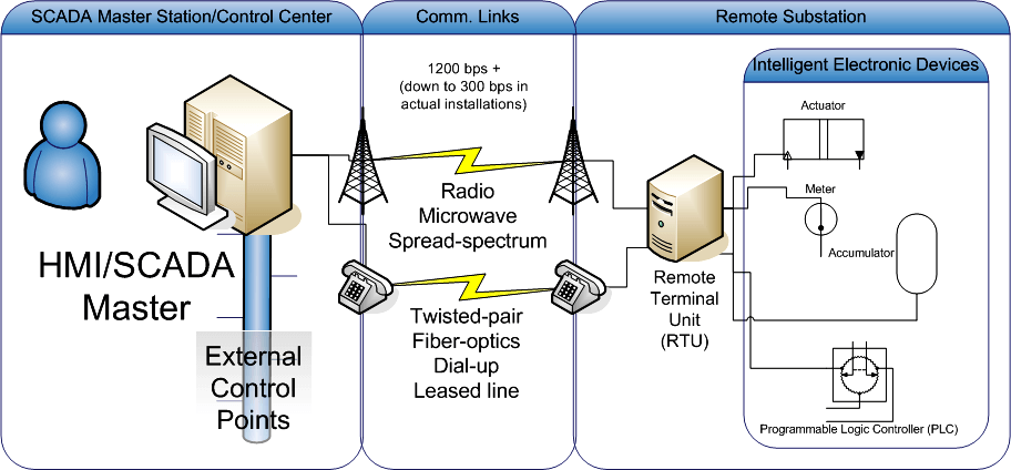
DNP3 (Distributed Network Protocol) is a set of communications protocols used between components in process automation systems. Its main use is in utilities such as electric and water companies. Usage in other industries is not common.
It was developed for communications between various types of data acquisition and control equipment. It plays a crucial role in SCADAsystems, where it is used by SCADA Master Stations (aka Control Centers), Remote Terminal Units (RTUs), and Intelligent Electronic Devices (IEDs). It is primarily used for communications between a master station and RTUs or IEDs.
ICCP, the Inter-Control Center Communications Protocol (a part of IEC 60870-6), is used for inter-master station communications.
What is DNP3?
DNP3 is a communications protocol used in SCADA / “remote monitoring” systems. It has become very popular because it’s “open”. Any manufacturer can develop DNP3 equipment that is compatible with other DNP3 equipment.
DNP3 uses a Master/Remote Model.
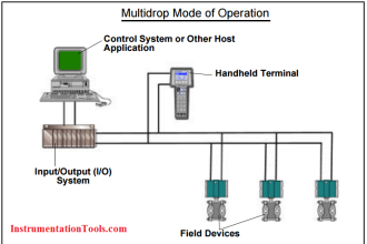
DNP3 is typically used between central masters andremotes that are spread widely. The master (think “Operating Center”) links the human (you) and the monitoring system. The remote (think “sub station”) provides the interface between the master and the actual device(s) being monitored or controlled.
The master and remote both use a library of common objects to exchange data. DNP3 protocol can be used reliably over media that may be subject to noisy interference.
DNP3 is an open, intelligent, robust, and efficient modern SCADA protocol. It can
- request and respond with multiple data types in single messages,
- segment messages into multiple frames to ensure excellent error detection and recovery,
- include only changed data in response messages,
- assign priorities to data items and request data items periodically based on their priority,
- respond without request (unsolicited),
- support time synchronization and a standard time format,
- allow multiple masters and peer-to-peer operations,
- and allow user definable objects including file transfer.
How do DNP3 Elements Communicate?
DNP3 uses 27 basic function codes to exchange data between Masters (think “Control Center”) and Remotes (think “pump yard”). Some of those function codes enable a Master to request and receive status info from a Remote. Other function codes enable a Master to change a Remote’s settings.
Other function codes are defined for a DNP3 Master to control the Remote – or gear next to the Remote. One function code is provided to enable the Remote to respond with an Unsolicited Message to particular events that occur in its area.
As you can see, most of the messages are issued by the DNP3 manager. Because the Unsolicited Message is capable of being initiated by a Remote, it is typically used to report alarms.
This notifies the DNP3 Master as soon as an alarm condition occurs, instead of waiting for the next request.
Understanding the DNP3 Object Library.
The DNP3 framework includes a library of objects that are used in many SCADA systems. This library is free for DNP Users Group members. Visit www.dnp.org for more. These standard objects include Binary Inputs. These will report things that have two states; power is on or off, an access panel is open or closed.
Another common object is an Analog Input that is used to report things that have a range of values. Exhaust fan speed can be anywhere from 40 to 400 RPM. Main power can vary from 110 to 128 VAC.
This library makes it easy for the manufacturer to design the DNP3 Remote responder to use these common objects to report to upstream Masters. It also makes it easier for Masters to integrate the data collected from Remotes and present it for you.
Without this framework of common objects, manufacturers must develop their own model for reporting status and providing control capability. These models, often very different, must then be ‘compiled’ into the Masters and converted into some kind of common objects for efficient management.
Another tool often found in these more ‘open’ frameworks is a proprietary interface or translation module to access and control the Remote.
Objects in the DNP3 library are divided into Groups and Variations. For example, the Analog Input group has six variations to provide 16 or 32 bit integer or floating point values with or without a status bitmap.
The Analog Event group has eight variations to provide 16 or 32 bit integer or floating point values with a status bitmap and with or without a timestamp.
Note that the Analog Event group does not include variations without a status bitmap.
Understanding DNP3 Layered Communication
DNP3 uses the layered communication model:
- The application layer combines several parts. Ther’s an application service data unit (ASDU). Then there’s the packaged object. An application protocol control info (APCI) block is added to make an application protocol data unit (APDU).
- The transport layer breaks the APDU into segments with a max size of 16 bytes and combines them with an 8-bit transport control header and 16-bit segment CRC separators into a transportFrame.
- The link layer adds a header to the control and address information. The packet is now ready for delivery.
These layers can be mapped to the four-layer model developed by the Department of Defense (you may recall the DoD origins of the Internet) with the DoD Internet Layer omitted.
If the packet will be sent over a LAN/WAN, the three DNP3 layers are rolled up into the application layer.
The assembled packet is wrapped in the Transport Control Protocol (TCP) by the transport layer, which in turn is wrapped in the Internet Protocol (IP) by the (somewhat obvious) internet layer.
The User Datagram Protocol (UDP) can also be used but presents some additional issues related to reliable delivery in congested networks.
The fourth layer is the Network Interface layer where the assembled packet is actually interfaced to some kind of transport media (for example, twisted pair copper, RG58 co-axial or fiber).
While this multi-layer model may seem a bit confusing, it effectively isolates the tasks of communication and ultimately assists in designing and implementing a network.
Traversing the Layers
To show this layered model, let’s look at a single DNP3 Read request over a LAN. The DNP3 Master wants to know the status of the Remote’s power and prepares a Read request message for that object.
After passing through all three DNP3 layers, the message is passed to the TCP/UDP transport layer. The transport layer adds a data block that IDs the Master port and the port where it expects the Remote DNP3 process to be listening for messages. The packet is then passed to the IP layer.
Here, a data block holding the IP and Media Access addresses of the Master and the Remote is added. Then, the full packet gets passed to the Network Interface layer.
The Network Interface layer checks media access and availability. It then places the packet on the media for transmission.
After working its way across bridges and through routers (something like “over the river and through the woods”) based on the IP info, the packet arrives at the Remote.
Here, it passes through the same four layers in the opposite order as it did at the Master. First, it is pulled off the media by the Network Interface layer. After checking that the packet is intact and valid, the Network Interface layer passes it to the IP layer.
The IP layer checks the Media Access and IP address and passes it on to the TCP/UDP layer where the target port is checked for connected applications. If an app is listening at the target port, the packet is passed to the Application layer. If the listening app is the Remote DNP3 process, the Read request is passed.
It moves through its three layers to check the request and see what info needs to be collected. The Remote response then follows the same path in reverse to reach the Master.
An DNP3 message passes through the protocol layers at both the manager and the agent. Each layer addresses a specific communication task.
An Aid for Troubleshooting
Knowing this layered model of DNP3 makes it easier to find and fix network problems. When there is a problem, you can simply trace it down, out one end, into, and up the other. LAN/WAN link and status lights provide show you to the Network Interface layer. ICMP echo requests and responses (Pings) provide some information regarding the proper functioning of the IP layer.
DNP3 processing indicators can be used to verify the passage of the DNP3 packet through the TCP/UDP layer and the functioning of the Application layer.
Each step can be verified independently until all steps are working correctly for end-to-end communication.
Benefits of DNP3
DNP3 Provides Multiplexing, Data Fragmentation, and More.
DNP3 is a layer 2 protocol. This means that it provides for:
- Multiplexing.
- Data fragmentation.
- Error checking.
- link control.
- Priority sorting.
It also provides layer 2 addressing services for user data.
DNP3 allows the various devices in process automation systems to talk. The DNP3 protocol is widely used for electrical, gas and water telemetry by utility companies. It is also possible for DNP3 to be utilized in other areas, though it is not as common.
SCADA Communications Uses DNP3 Protocol.
SCADA systems use the DNP3 protocol for use between system components. The DNP3 protocol provides for communication between the SCADA system master, RTUs, and Intelligent Electronic Devices (IEDs).
DNP3 was developed to meet the need for a standard protocol that would allow SCADA system components developed by differing vendors to talk. Using IEC 60870-5 as a base, DNP3 was created as an open protocol for use in these cases.
This protocol was available for prompt use within SCADA networks, and catered to the specs laid out by North American organizations.
DNP3 Provides Communications Reliability for Utilities.
DNP3 ensures the reliability of communications within the harsh environments of utilities. The protocol is able to avoid being distorted by EMI, legacysystem components, and poor transmission due to DNP3’s communications format.
Although the protocol has error checking, DNP3 is not secured. This is an important consideration during SCADA planning.
Why is it so popular ?
There are a few reasons why DNP3 is so powerful, and commonly used in telemetry systems:-
- It is a standard and open. This means that the “language” is readily available and all DNP3 devices communicate using the same language. Early RTU’s communicated using proprietary protocols which meant the language they communicated in was known only to other products produced by the same vendor. Today, many devices are multi-lingual in that they will communicate using their proprietary protocol but also allow communications using the DNP3 protocol, this has been done by many vendors to allow a gradual upgrade of their network to DNP3 over time.
- It is a routing protocol. This is a particularly important and key feature of the DNP3 protocol in that it can communicate via different communication networks to reach the destination of the message. For example, the SCADA machine may be connected to an Ethernet connection but the RTU may be on a radio connection, DNP3 is able to be routed through from the Ethernet connection to the Radio connection via an intermediate RTU. This sounds complex, but in simple terms it would be like you talking across a phone connection to your friend, and them relaying the message to someone on a nearby walkie talkie. The power of DNP3 is that this can be done very easily in most modern RTU’s without the need for complex I/O mapping.
- It makes good use of the communications channel. DNP3 has been designed to be able to operate on both high speed Ethernet networks and slow speed radio networks and is very good at “only communicating when necessary”. For example, when a pump turns on or off DNP3 will send a message through notifying the SCADA of that one change. Fixed polling protocols, like MODBUS are unable to achieve this as they have to constantly update all data by polling. Back to our human analogy, this would be like you continually asking your friend to tell you what the traffic light is showing, in a polling protocol example the friend would be constantly saying green, green, green, green then red, red, red every second or so. With DNP3, the friend would only tell you when the light changes therefor using up much less bandwidth.
- Many friends at once. What this point number 3 above means is that you could hold conversations with many friends at once and this is indeed the power of DNP3, allowing many pumping stations, substations or gas wells to communicate on the same network.
Article Source: dpstele


Excellent articles and a good job Sir. Very nicely explained. Keep it up!
Excellent articles