This is a PLC Program for controlling the sequence of conveyors and interlocking them.
PLC Conveyor Interlock
Problem Description
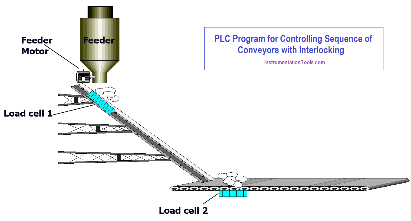
A feeder drops material on the conveyor which sends material for further process through one more conveyor. The conveyor must start automatically when the material is dropped.
Implement a PLC program for this application using ladder diagram language.
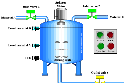
Problem Diagram
Problem Solution
In this system, we will consider S7-300 PLC and TIA portal software for programming.
The feeder has a motor mounted to feed material on conveyor belts.
Load cells are installed at the bottom of conveyor belts to detect if material is present on the conveyor belt.
When material falls on the conveyor belt 1, motor 1 should start, and when material is present on the conveyor belt 2, motor 2 remains ON.
Switches can also be used sometimes to detect material’s presence. But for more reliable operation, Load cells can be used as shown in the diagram above.
List of Inputs/Outputs
Inputs List
- START PB :- I0.0
- STOP PB :- I0.1
- Load cell 1 :- I0.2
- Load cell 2 :- I0.3
Outputs List
- Cycle ON :- Q0.0
- Conveyor 1 motor :- Q0.1
- Conveyor 2 motor :- Q0.2
- Feeder motor :- Q0.3
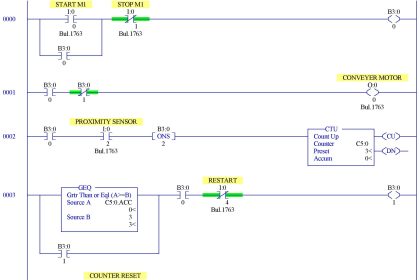
PLC Controlling Sequence of Conveyors with Interlock
Program Explained
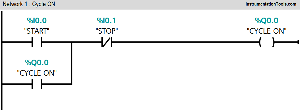
Network 1:
Cycle ON (Q0.0) lamp will start when START PB (I0.0) will be pressed and cycle can be stopped by pressing STOP PB (I0.1).
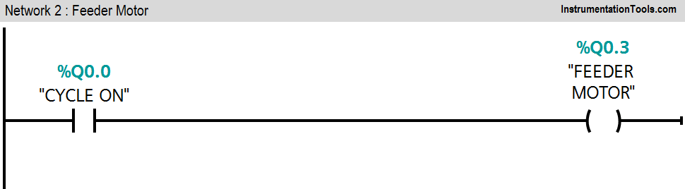
Network 2:
Feeder motor (Q0.3) will be ON when cycle is ON.
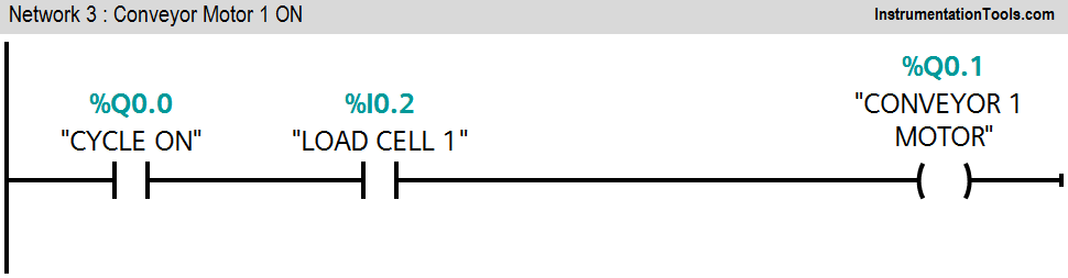
Network 3:
If cycle is ON and load cell 1 feedback is detected, conveyor motor 1(Q0.1) will be ON.
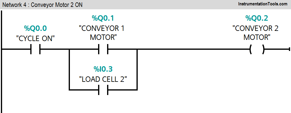
Network 4:
If cycle is ON and Conveyor 1 (Q0.1) or load cell 2 feedback (I0.3) is detected, conveyor 2 motor (Q0.2) will be ON.
Note :- Above application may be different from actual application. This example is only for explanation purpose only. We can implement this logic in other PLC also. This is the simple concept of conveyor logic and interlocking them, we can use this concept in other examples also.
All parameters considered in example are for explanation purpose only, parameters may be different in actual applications. Also all interlocks are not considered in the application.
Author: Bhavesh
If you liked this article, then please subscribe to our YouTube Channel for PLC and SCADA video tutorials.
You can also follow us on Facebook and Twitter to receive daily updates.
Read Next:
- Tank Heating Control using Heater
- PLC Analog Input Sampling
- Automatic Empty Bottle detection using PLC
- PLC Two Way Switch Logic
- Counters using PLC


Hello sir! Can you restore the download pdf option that you had before? It was great!
Thank you
Hi, We have an issue with the pdf download. soon we will restore the option.
Great news! Thank you sir for this information and keep on your effort to this very helpfull site!
Hello, I see you have not yet solved the problem with downloading pdf files, can it by the end of the year? I’m very much in my personal training. I really like and am fan of your site 🙂
Hopefully, We are working on it.