Inst ToolsInst ToolsInst Tools
  • Courses
  • Automation
    • PLC
    • Control System
    • Safety System
    • Communication
    • Fire & Gas System
  • Instrumentation
    • Design
    • Pressure
    • Temperature
    • Flow
    • Level
    • Vibration
    • Analyzer
    • Control Valve
    • Switch
    • Calibration
    • Erection & Commissioning
  • Interview
    • Instrumentation
    • Electrical
    • Electronics
    • Practical
  • Q&A
    • Instrumentation
    • Control System
    • Electrical
    • Electronics
    • Analog Electronics
    • Digital Electronics
    • Power Electronics
    • Microprocessor
  • Request
Search
  • Books
  • Software
  • Projects
  • Process
  • Tools
  • Basics
  • Formula
  • Power Plant
  • Root Cause Analysis
  • Electrical Basics
  • Animation
  • Standards
  • 4-20 mA Course
  • Siemens PLC Course
Reading: PLC Program for Boolean Expression
Share
Font ResizerAa
Inst ToolsInst Tools
Font ResizerAa
  • Courses
  • Design
  • PLC
  • Interview
  • Control System
Search
  • Courses
  • Automation
    • PLC
    • Control System
    • Safety System
    • Communication
    • Fire & Gas System
  • Instrumentation
    • Design
    • Pressure
    • Temperature
    • Flow
    • Level
    • Vibration
    • Analyzer
    • Control Valve
    • Switch
    • Calibration
    • Erection & Commissioning
  • Interview
    • Instrumentation
    • Electrical
    • Electronics
    • Practical
  • Q&A
    • Instrumentation
    • Control System
    • Electrical
    • Electronics
    • Analog Electronics
    • Digital Electronics
    • Power Electronics
    • Microprocessor
  • Request
Follow US
All rights reserved. Reproduction in whole or in part without written permission is prohibited.
Inst Tools > Blog > PLC Tutorials > PLC Program for Boolean Expression

PLC Program for Boolean Expression

In this article, you will learn the PLC program for Boolean expression and learn the plc automation with basic logic.

Last updated: March 25, 2024 2:35 pm
Editorial Staff
PLC Tutorials
No Comments
Share
4 Min Read
SHARE

In this article, you will learn the PLC program for Boolean expression and learn the plc automation with basic logic.

Contents
PLC ProgramBoolean to PLC ConversionInputsOutputsBoolean Expression Ladder LogicLogic DescriptionTest Results

Please note: The logic diagram example provided here is designed for educational use for students and engineers to learn PLC fundamentals.

PLC Program

Problem Statement

Design a PLC ladder logic for the following Boolean Expression.

We are using toggle Inputs to control the output.

Convert the given boolean logic to PLC ladder logic.

Y = A(BC+D)

Boolean to PLC Conversion

Watch the below PLC tutorial video to learn the basics.

PLC Logic - Boolean Expression Based Example

Inputs

Digital Inputs:

The list of inputs are listed.

A: I0.0

B: I0.1

C: I0.2

D: I0.3

Outputs

Digital Outputs:

The list of outputs are listed.

Y: Q0.0

Boolean Expression Ladder Logic
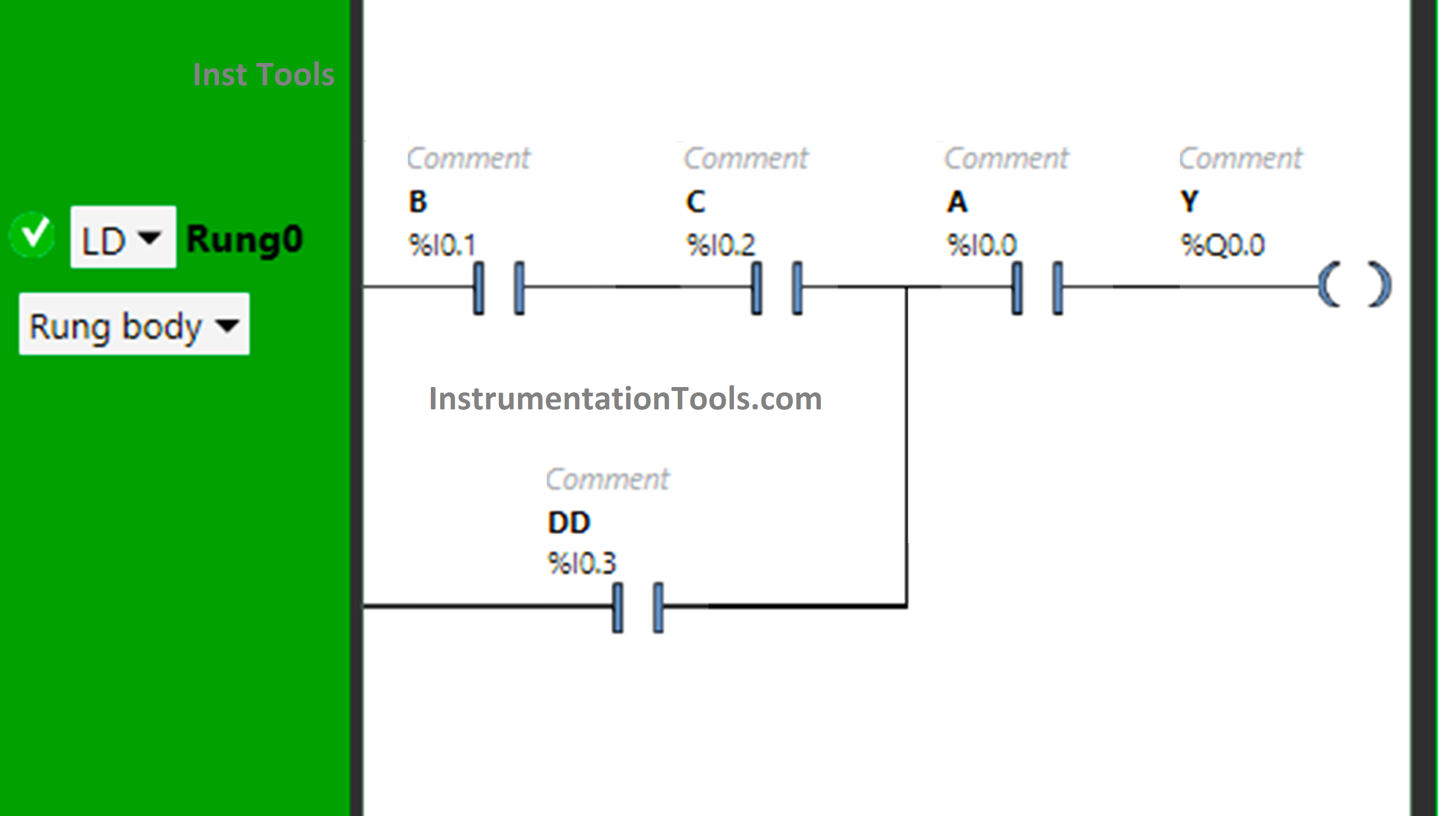
PLC Program for Boolean Expression

Logic Description

  • We used the EcoStruxure Machine Expert Basic software for PLC programming.
  • In the above program, Normally Open Contacts are used for inputs A, B, C, and D.
  • Input B and Input C are connected in series, thus implementing AND Logic Gate.
  • The Input D is connected in parallel with the output of BC, thus implementing OR Logic Gate.
  • Then there is again the implementation of AND Logic Gate as the Input A is connected in series with the output of BC+D.
  • For output Y (Q0.0) to be ON, either Input B, Input C, and Input A should be ON, or Input D and Input A should be ON.
  • Turning OFF Input A will turn OFF  Y (Q0.0), even if all remaining Inputs are turned ON.

Test Results

Now we simulate the program with different input statuses.

When Input B, Input C, and Input A are ON
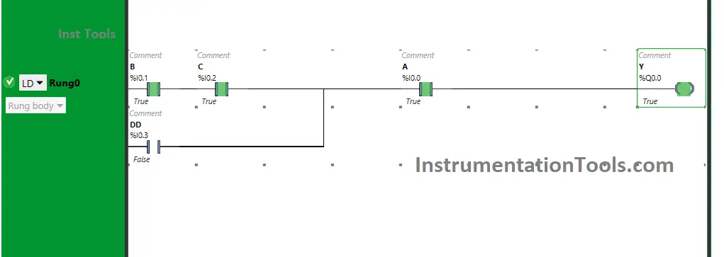
Boolean Expression Ladder Logic

When  Input B, Input C and Input A are turned ON, the output Y (Q0.0) will turn ON. If one of  these Inputs are turned OFF, Y(Q0.0) is turned OFF. These inputs are used as Normally Open Contacts and are connected in series.

Therefore, all the inputs should be ON so that the output Y (Q0.0) will turn ON. The output Y (Q0.0) will not turn ON, if all the inputs i.e., B, C and D are not turned ON.

When both Input D and Input A are ON
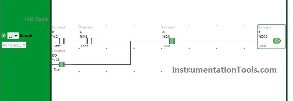
PLC Boolean Conversion

Y (Q0.0) will turn ON When Input D and Input A are turned ON. As the input D is connected in parallel with the output of BC, instead of turning ON the inputs B and C, the input D will also allow the signal to pass when turned ON.

The inputs D and A are connected in series. Therefore, turning ON the inputs D and A will also turn ON the output Y (Q0.0). If only one input is turned ON, the output Y (Q0.0) will not turn ON.

If you liked this article, please subscribe to our YouTube Channel for PLC and SCADA video tutorials.

You can also follow us on Facebook and Twitter to receive daily updates.

Read Next:

  • Programmable Logic Controller Test
  • Memory Bits and Set Coils in Ladder Logic
  • PLC with 2 Toggle Switches and 4 Motors
  • PLC based Door Open and Closing System
  • DeMorgans Theorems using Ladder Diagram
Don't Miss Our Updates
Be the first to get exclusive content straight to your email.
We promise not to spam you. You can unsubscribe at any time.
Invalid email address
You've successfully subscribed !

Continue Reading

What is a Line Choke or Reactor in a VFD?
PLC Sequential Operation Example Program
Example of Controlling the PLC Output using Push Buttons
Network Switch Requirement in SCADA and DCS Architecture
PLC Digital Input and Digital Output Modules
Concept of Latching in PLC
Share This Article
Facebook Whatsapp Whatsapp LinkedIn Copy Link
Share
Leave a Comment

Leave a Reply Cancel reply

Your email address will not be published. Required fields are marked *

Stay Connected

128.3kFollowersLike
69.1kFollowersFollow
210kSubscribersSubscribe
38kFollowersFollow

Categories

Explore More

PLC Program for Mixing Tank
Single Loop Controller Questions
Count the Number of Cartons in a Storage Area PLC Logic
RSLogix 5000 PLC Programming Procedure
Scheduled Daily Plant Watering PLC Program
PLC Program for Temperature Control using Thermostat
PLC Programming: Sorting and Distribution of Boxes by Height
Electrical Earthing Calculations

Keep Learning

MCQ on PLC (Programmable Logic Controller)

MCQ on PLC (Programmable Logic Controller)

Free Download PLC Book

Free Download Programmable Logic Controller (PLC) Book

PLC program for bread oven

Bread Oven Control in Auto and Manual Modes PLC Program

Instruction List in PLC Programming

What is an Instruction List? – PLC Programming

ControlLogix

Difference Between CompactLogix and ControlLogix

Marking Machine

PLC SCL Program for Marking Machine

Global Data Blocks in PLC

What is a Data Block? Global Data Blocks in PLC

Ladder Logic Programming Examples

Ladder Logic Programming Examples

Learn More

Working of Woodward Governor 505

Overview of Woodward Governor 505

Allen-Bradley MicroLogix PLC Wiring

Programmable Logic Controller (PLC) Questions and Answers – 8

Patch Panel

What is a Patch Panel? Types and Uses in Networking

remote seal capillary type dp transmitter

Closed Tank Remote Seal Capillary type DP Transmitter

Steam Pressure Taps Primary Block Valves Glands and Bonnets Leaks

Instrument Steam Pressure Taps Primary Block Valves Glands and Bonnets Leaks

Siemens Process Mode

Test and Process Modes in Siemens PLC

PN Junction Questions & Answers

Measurement and Instrumentation Objective Questions – Part 5

Non‐contact RADAR Level Transmitter Pulse

Non Contact RADAR Level Transmitter Principle, Limitations, Design, Installation and Calibration

Menu

  • About
  • Privacy Policy
  • Copyright

Quick Links

  • Learn PLC
  • Helping Hand
  • Part Time Job

YouTube Subscribe

Follow US
All rights reserved. Reproduction in whole or in part without written permission is prohibited.
Welcome Back!

Sign in to your account

Username or Email Address
Password

Lost your password?