Level the parameters that exist in virtually every industrial process, there are many ways to measure the level, the simplest is to use the sight glass. By using a sight glass, the height of liquid in a vessel / vessel will be physically visible, so as to make the scale on sight glass, we can immediately determine what percentage of the liquid surface height of a tall vessel / tank / vessel.
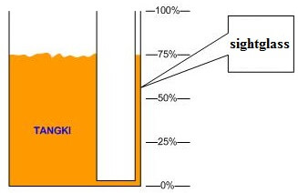
In the picture, a tank connected by a transparent hose using a scale of 0-100% of the total height of the tank. This level measurement principle utilizing the properties of the liquid will fill all the space that he passed on the associated vessel.
Height of liquid in the tank will be the same as the height of a liquid residing on a transparent hose that serves as a sight glass. We can directly determine height (level) of liquid inside the tank by looking at the height of a liquid residing on a transparent hose (sight glass) is.
However, this information can only be served directly in the field, or directly see where the transparent hose attached. Level measurement method is relatively inexpensive.
Pressure Hydro static
Any liquid that occupies a vessel / vessel / tank, will have a hydrostatic pressure in proportion to the level of the liquid, with assume densities (sg = specific gravity) of his remains.
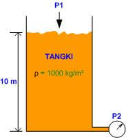
The picture above is an open tank (surface connected to the atmosphere), where there will be work pressure P1 at atmospheric pressure, which then will we ignore because we will measure pressure “gauge”.
Assume melting substance is water, with a density of ρ = 1000 kg / m³. With the height of the surface from the bottom of the tank where pressure measurement is 10 meters. Then the P2 pressure acting on the pressure gauge is:
ρ = density of water = 1000 kg / m³
g = gravity = 9.8 m / s²
h = height of base water tank = 10 m
P2 = ρ × g × h
P2 = 1000 kg / m³ × 9.8 m / s² × 10 m
P2 = 98000 kg / m³ × m / s² × m
P2 = 98000 kgmm / m³s²
P2 = 98000 kgm / s²m²
P2 = 98000 N/m2
P2 = 98000 Pascal
P2 = 98 kilopascals = 14.2136983 PSI = 0.9993218887 kg / cm²
1 kilopascals = 0.1450377377 PSI (pounds per square inch)
1 kilopascals = 0.01019716213 kg / cm²
Consider the following table:
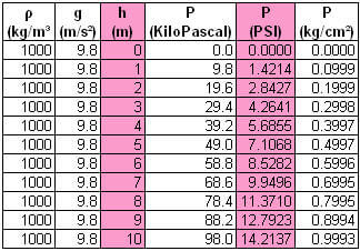
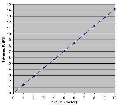
From the table and from the graph, we can see that the level (h) is proportional to the pressure (P), so by measuring the pressure at the point of the tank bottom, we can know the level of water in the tank. For example: Results pressure on the bottom of the tank, we get 4.2641 PSI, then by reversing the above calculation, we would get a level of 3 meters.
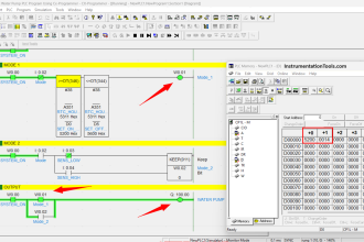
How to present levels in the DCS, PLC or Controller?
Pressure gauge is installed at the bottom of the tank before, can be replaced by using a pressure transmitter calibrated measuring ranges (range) input 0 to 14.2137 PSI, let me easily (not recommended in practice), we round it off to 14PSI, and output , for example, 4-20 mA (milli-amperes).
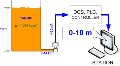
4-20 mA signal that represents the input signal from the pressure transmitter in this instance 0-14 PSI calibrated transmitter for 4-20mA output, transmitted to a receiver that can be either DCS, PLC or controller, which is connected with the station that serves as MMI (Man -Machine Interface) or HMI (Human-Machine Interfacer), the DCS, PLC or controller, the 4-20mA signal on-scaling longer a form of engineering units (meters) so that the variation of 0-10 meter level in the tank, can be displayed 0 -10 meter (engineering unit) on the HMI / MMI.
So that the overall representation of the signal to be:
- 0-10 meter level in the tank
- 0-14 PSI hydrostatic pressure on the input Trasmitter
- 4-20mA input signal transmission in the DCS, PLC, controller
- in DCS, PLC, controller-scaling into engineering units back (0-10 meters), with no attention to the process of analog to digital conversion
- The display on the MMI / HMI in the form Engineering Unit (meters)
Determine Range Differential Pressure Transmitter To Measure Level
The level measurement can be done by utilizing the hydrostatic pressure of the liquid inside the tank to be measured its level.
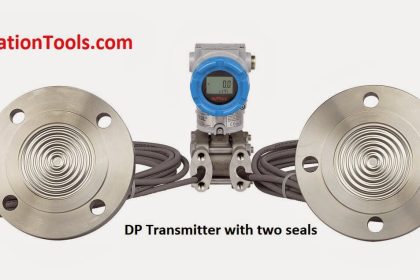
To measure the hydrostatic pressure caused by the liquid level in a tank, can be used a differential pressure transmitter with a measuring range (range) the corresponding input.
Consider the example in the image below:
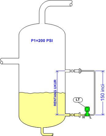
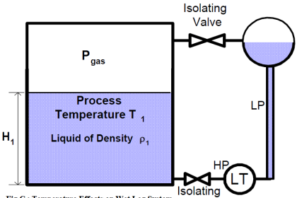
A vessel with a working pressure P1 = 200 PSI, has a measuring range for liquid high as 150 inches (3.81 meters). The question is, what is the input range for the level transmitter (differential pressure transmitter) which will be used?
Before continuing, we know that on both sides (H and L) Differential pressure transmitter works work pressure vessel of the same (200psi), if dp = H – L = (P1 + P hydrostatic) – P1 = Phydrostatic, then pressure work on the DP transmitter is P hydro static only. To that end, the next calculation, only P hydro static are included in the count.
If the liquid to be measured its level is water, it is easy once we determine the level transmitter range to be used, namely 0-150 “H 2 O, so that we can calibrate the transmitter 0-150″ H 2 O. Or to obtain the hydrostatic pressure, we specify the formula to get the hydrostatic pressure, as follows:
ρ = 1000 kg / m³
g = gravity = 9.8 m / s²
h = 150 inches = 3.81 meters)
P = ρ × g × h
P = 1000 kg / m³ × 9.8 m / s² × 3.81 m
P water = 37338 Pascal
P water = 150 “H 2 O
How the case if the liquid contained in the vessel is a liquid that has a density of (or specific gravity = SG) are different, for example, 800 kg / m³ (0.8 g / cm³) for condensate. Is the level transmitter range 0-150 “H 2 O is still valid? Of course not, because of the hydrostatic pressure caused by liquid which has a different SG will be different. Now let us count, what is the hydrostatic pressure caused by condensate at a height of 150 inches levels?
ρ = 800 kg / m³
g = gravity = 9.8 m / s²
h = 150 inches = 3.81 meters)
P = ρ × g × h
P = 800 kg / m³ × 9.8 m / s² × 3.81 m
P condensate = 29870.4 Pascal Pascal unit <<< Where is this? Click here
When compared with the hydrostatic pressure of water, the hydrostatic pressure of condensate at the same altitude, the smaller.
Now let’s use a practical formula. Because the water used as a benchmark or standard unit of pressure, with units Inch H 2 O (inches of water), then we can compare the height of a liquid that is already known to SG her with water that has the same height (in this example 150 “), then multiplied by the hydrostatic pressure of the water. Mathematically be written as follows:
P condensate = (SG condensate / water SG × Pair
P condensate = (800/1000) × 37338 Pascal
Because 37338 Pascal = 150 “H 2 O, then:
P condensate = (800/1000) x 150 “H 2 O
P condensate = 120 “H 2 O
So that the differential pressure transmitter that we use as our transmitter level calibration with input range 0-120 “H 2 O for measuring range 0-150 inches tall height condensate.
Dry and Wet Leg Leg of Level Transmitters
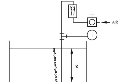
PU = air pressure
PL = pressure on the sides L transmitters
PH = pressure side H transmitter
LT = level transmitter
PCV = pressure control valve (pressure regulator)
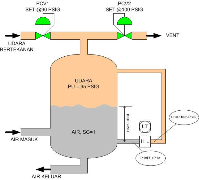
The picture above is a pressurized tank that serves to squeeze the water out of the tank.Pressure is coming from the outside air pressure which is guarded by two regulators, PCV1 is set at 90 PSIG and PCV2 at 100 PSIG, if the pressure in the tank falls below 90 PSIG, the PCV1 will open proportionally provide additional air,
if the pressure inside tank rise above 100 PSIG, the PCV2 opens proportionally, remove the excess pressure to the atmosphere. This configuration used in water utility (water Indonesian, which means the air instead of water), such as for water demand was intermittent or constant or other related applications.
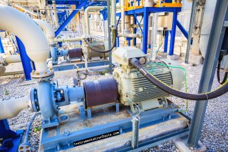
Incoming water comes from a pump. Why not just channeled to pump water from the utility?This is due water usage is not constant, which sometimes exceeds the delivery capacity of the pump. Why not just enlarged the capacity of the pump? Ordinary …. this is due to cost considerations. The greater the capacity of the pump, the more expensive.
In this post is not being discussed on the pump and the water utility. Which will be highlighted in this post is the installation level transmitter to determine the water level in the tank. LT (Level Transmitter) is used to measure the water level in the tank is used DP transmitter. How DP can measure the level.
Why the low side of the LT connected to the tank top? This is due to clicking equalize air pressure on the side of H and L of the transmitter, so that LT is measured by hydro static pressure of water is directly proportional to the water level in the tank.
On the state of the water level in the tank zero, or the water level touches the point of measurement side of the H-her or in other words the tank is empty, then the transmitter does not detect any hydro static pressure, or (dp = PH-PL = 95 + 0-95 = 0).
The explanation above describes the configuration of the transmitter with the method of dry-leg. Why is it called dry leg? Because the sensing line transmitter is allowed to dry. (perhaps sensing line is termed the leg, foot)
What if the gas is in the upper side of the tank can condense at temperatures of work? For example condensate from the separation of oil-gas-condensate?
Predictably, the gas will condense into the low side sensing line, and of course, will affect the measurement accuracy, as SG (specific gravity) condensate will contribute hydrostatic pressure on the L.
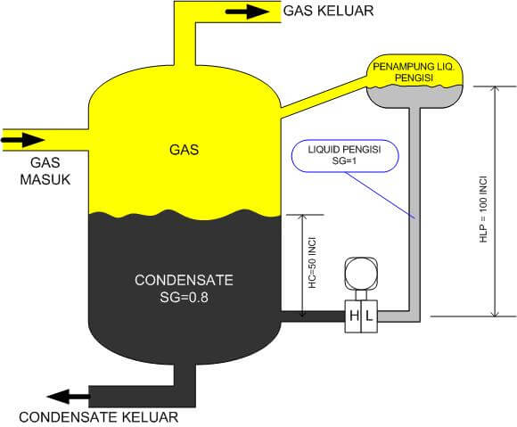
To overcome this problem, the method is applied wet leg, that is by filling in the low-side sensing line with a known liquid SG her. In this example for instance water, which has SG = 1.
There is little difference in treating dp transmitter which is implemented in level with wet leg. For example, the column height of the low-side sensing line in the example above is 100 inches, resulting hydrostatic pressure 100inH2O.
So that, when the tank is empty or the level of condensate touching a high side sensing point of LT, then the transmitter will measure pressure dp dp = PH-PL = 0-100 = -100 inH2O.
Well then that dp transmitter at zero trim, so its zero measurement has real pressure of minus 100inH2O. and when trimmed zero in these circumstances, the transmitter will send a signal to 0% (4mA for example).
Calculation details can be developed with reference to the previous post.
In addition to avoid measurement errors gas condensation, wet leg can also be useful when the fluid being measured.
In the wet leg, the actual measured value dp is always negative.
Also Read: DP Level Transmitter Calibration Procedure


Well written, good diagrams, easy to follow.
Nice one
Straight forward, easy to follow ideal teaching notes
For more easy application of DP transmitter, High side of DP transmitter is connected to Wet leg side and Low side is connected to other hand.
In this case, the calibration range can be applied to 0-100inchH2o and Reverse output set is required to the transmitter configuration without any additional action such as zero elevation required..