When you are working with PLC, you need to know what types of voltages are generally available in it; so that you can do the wiring accordingly. Not just power supply, but we must also be related to the input and output voltage required.
Every PLC manufacturer has their own set of voltage and current ranges according to the module and CPU they provide. In this article, we will learn the PLC operating voltages generally available everywhere.
PLC Power Supply
In standard, PLC operates in four types of voltages – 24V DC, 24V AC, 110V AC, and 240V AC. In some PLCs, only the CPU requires a power supply and the IO modules get supply from the CPU backplane, whereas in some PLCs, all the modules including CPU, inputs, and outputs require a power supply.
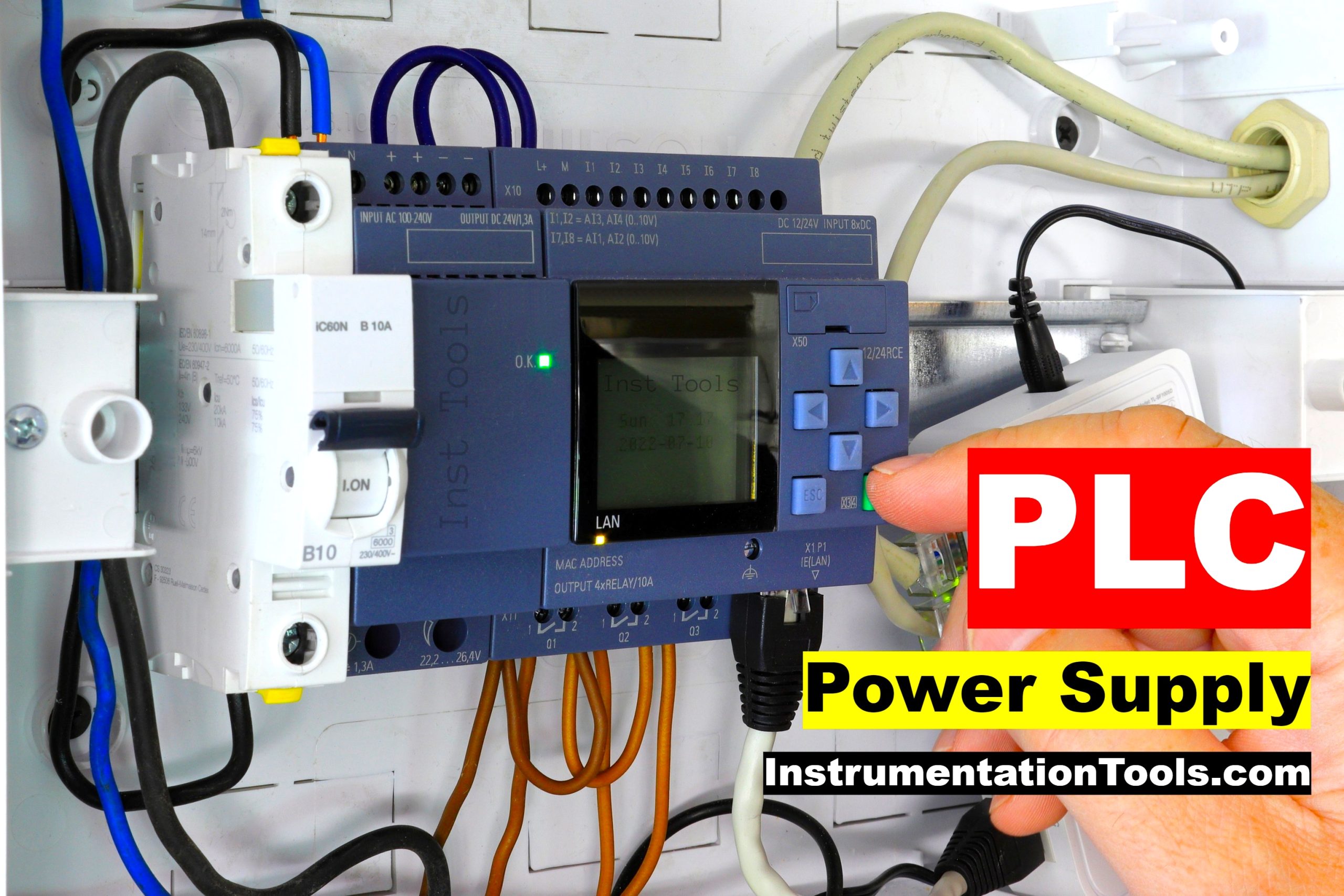
In any case, you will require a SMPS or transformer in the PLC panel, for converting raw power voltage. In AC supply voltage, some PLC’s offer a range of voltage from 110-240V AC.
Every power supply point in the PLC has an earthing point, for providing safety to the PLC in case of any surge or short circuit. When an AC supply is used, it is mostly equipped with a protective fuse inside.
DC supply too has a fuse inside, but for AC supply, it is compulsory to use it for the high amount of voltage involved. When the rated voltage is given in the CPU, it means that the voltage you are providing has been stabilized properly and controlled to a great extent.
But, it is not practical for voltage to remain constant at 24V or 240V. So, a range of rated voltage comes for a PLC like 20-28V DC or 220V-245V AC. This range is predefined in every PLC so that you get an area of power supply for working with them efficiently, without any problem.
Power Supply for IO Modules
Now, let us come to our next topic for the power supply required for IO modules. As discussed earlier, two types of power supplies are available – one where the module is powered by the CPU backplane itself and one where the module requires an external power supply.
When using the backplane, every CPU has a rating for mA that it will provide as a load to the modules connected.
For example, if a CPU has a rating of 24VDC – 450mA, then it will also specify that the CPU backplane can provide this much of current to the IO modules and you can connect only that amount of modules with the CPU rack.
Also, each module will specify how much current it will take when connected on a backplane bus. This can help you select the appropriate modules and CPU for a specific application.
Coming to the second type of power supply, there are some modules that require an external power supply. So, in that case, you have to choose an SMPS or transformer with a higher current and load rating accordingly. This can, in turn, power up both the CPU and modules properly and also power up other components of the panel which require the same supply.
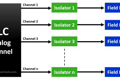
Power Supply for Field Instruments
Field wiring for a PLC also mostly requires DC voltage for instruments and AC voltage for high-power devices. So, the above four voltages mentioned earlier work the same for IO module common supply wiring.
Also, remember that there is mostly a battery backup inside the PLC apart from the standard power supply. This ensures that the program inside the memory of the PLC remains intact in case of any power outage.
Power Supply Selection for PLC
When selecting the power supply, it is thus necessary to consider the following parameters generally – rated voltage, rated current, rated power, ripple and noise, voltage adjustable range, voltage tolerance, line regulation, and load regulation.
Once you have selected the right power supply, you can then wire the CPU and modules to power it up properly.
In this way, we understand the concept of PLC operating voltages.
If you liked this article, then please subscribe to our YouTube Channel for Instrumentation, Electrical, PLC, and SCADA video tutorials.
You can also follow us on Facebook and Twitter to receive daily updates.
Read Next:
- Why 24 Volts DC Power Supply?
- VFD Commissioning Procedure
- Industrial Automation Checklists
- T-Junction Traffic Lights PLC Logic
- PLC Start-up Organization Block