You may have wondered how is it possible to check the current flowing in the three-phase lines, as the current is of large quantity and the standard meters do not operate at high currents. So, to measure the current, a device called a current transformer is used.
A current Transformer is a device that is surrounded by a live phase wire in a three-phase system, to measure the current flowing through it.
In this post, we will learn the concept of a current transformer.
What is a Current Transformer?
As the name implies, it is a type of transformer. The current transformer comes under the working similarity of a step-down transformer.
The current transformer (CT) converts high voltage current flowing through its primary winding (phase wire) to a low voltage current flowing through its secondary winding (to the internal ammeter). The meter will then automatically scale or calibrate inside to show the original value.
For example, suppose the ratio of CT is 1000:5 (in terms of current); so for a maximum primary current of 1000 A, the secondary current will be 5 A. Because, a low current is also safe for monitoring in a circuit, rather than monitoring such a large current.
Such large currents will easily damage the measuring circuits. If you are installing an energy meter in the panel, then three wires from three current transformers (R, Y, and B) will come together in the meter; so that all three currents can be shown.
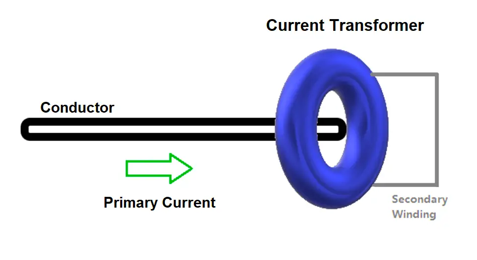
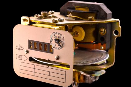
Refer to the above image. As you can see, the CT is mounted on a conductor carrying the main primary current. The output of the transformer is a secondary winding wound on it, which converts high current into the low current, and then fed to an ammeter.
The meter used should also be in the same ratio as the transformer. If the ratio is mismatched, then the reading also will show as a wrong value. The direction from where the current flow starts is termed as P1 and the output side is termed as P2. These terminals are marked in the transformer.
When you mount the transformer on the conductor, see to it that the P1 side faces the incoming current and the P2 side faces the outgoing current. If the connection is wrong, then the value will not show properly.
The output of the transformer has two terminals – S1 and S2. Make sure to connect it properly to the meter as per its terminals.
Do not get confused with its working. It is very similar to a transformer. The conductor through which the current is passing produces an electromagnetic field that excites the magnetic coil windings of the secondary side and induces a current in it.
The Ratio of Current Transformer
Let us now understand how the ratio of CT is interpreted and made to function. As discussed earlier, a CT of 1000:5 means a 5A secondary current for a primary current of 1000A. 1000:5 brings us a ratio of 200:1.
This means that the current should be proportional in this range. According to the standard turns ratio formula of a transformer, TR=NP/NS=IS/IP;
where TR is the turns ratio, NP is the number of primary windings, NS is the number of secondary windings, IS is the secondary current and IP is the primary current.
By increasing the number of secondary windings, NS, the secondary current can be made much smaller than the current in the primary circuit being measured because as NS increases, IS goes down by a proportional amount.
In other words, the number of turns and the current in the primary and secondary windings are related by an inverse proportion.
Current Transformer Important Points
One thing to remember is that the secondary windings should never be kept open. This is because the load flowing from the primary current should be equally dissipated somewhere in the current transformer.
For this reason, secondary winding is provided. So, if there is no path for the current to flow in the secondary winding, then there will be no demagnetizing flux due to the secondary current.
Due to the absence of the counter ampere-turns of the secondary, the unopposed primary emf will set up an abnormally high flux in the core. This flux will produce core loss with subsequent heating, and a high voltage will be induced across the secondary terminal.
Due to such a high voltage, the insulation of the winding will break down. Then, that CT will be of no use. So, it is always necessary to keep the secondary winding connected.
It is to be noted that a standard clamp meter that you use to measure current is also a type of current transformer. You must have seen how you clamp the wound around the wire. It is the same concept as the current transformer.
In this way, we understand the concept of the current transformer.
If you liked this article, then please subscribe to our YouTube Channel for Electrical, Electronics, Instrumentation, PLC, and SCADA video tutorials.
You can also follow us on Facebook and Twitter to receive daily updates.
Read Next:
- What is a Substation?
- Motor Cooling Methods
- Flame Retardant Cables
- SCADA in Power System
- Single and Multi-Core Cables