Inst ToolsInst ToolsInst Tools
  • Courses
  • Automation
    • PLC
    • Control System
    • Safety System
    • Communication
    • Fire & Gas System
  • Instrumentation
    • Design
    • Pressure
    • Temperature
    • Flow
    • Level
    • Vibration
    • Analyzer
    • Control Valve
    • Switch
    • Calibration
    • Erection & Commissioning
  • Interview
    • Instrumentation
    • Electrical
    • Electronics
    • Practical
  • Q&A
    • Instrumentation
    • Control System
    • Electrical
    • Electronics
    • Analog Electronics
    • Digital Electronics
    • Power Electronics
    • Microprocessor
  • Request
Search
  • Books
  • Software
  • Projects
  • Process
  • Tools
  • Basics
  • Formula
  • Power Plant
  • Root Cause Analysis
  • Electrical Basics
  • Animation
  • Standards
  • 4-20 mA Course
  • Siemens PLC Course
Reading: PLC based Automatic Bell System for a School
Share
Notification Show More
Font ResizerAa
Inst ToolsInst Tools
Font ResizerAa
  • Courses
  • Design
  • PLC
  • Interview
  • Control System
Search
  • Courses
  • Automation
    • PLC
    • Control System
    • Safety System
    • Communication
    • Fire & Gas System
  • Instrumentation
    • Design
    • Pressure
    • Temperature
    • Flow
    • Level
    • Vibration
    • Analyzer
    • Control Valve
    • Switch
    • Calibration
    • Erection & Commissioning
  • Interview
    • Instrumentation
    • Electrical
    • Electronics
    • Practical
  • Q&A
    • Instrumentation
    • Control System
    • Electrical
    • Electronics
    • Analog Electronics
    • Digital Electronics
    • Power Electronics
    • Microprocessor
  • Request
Follow US
All rights reserved. Reproduction in whole or in part without written permission is prohibited.
Inst Tools > Blog > PLC Tutorials > PLC based Automatic Bell System for a School

PLC based Automatic Bell System for a School

Last updated: March 4, 2021 4:02 pm
Editorial Staff
PLC Tutorials
No Comments
Share
3 Min Read
SHARE

In a school, bell is activated by the PLC system. The bell will ring automatically at a fixed timing for 5 seconds interval. Write PLC program for this system using ladder logic programming.

Contents
Automatic Bell SystemSolutionList of Inputs/OutputsLadder diagram for Automatic School Bell SystemLogic Description

The required bell timings are at school start time, break time and school end time.

Automatic Bell System
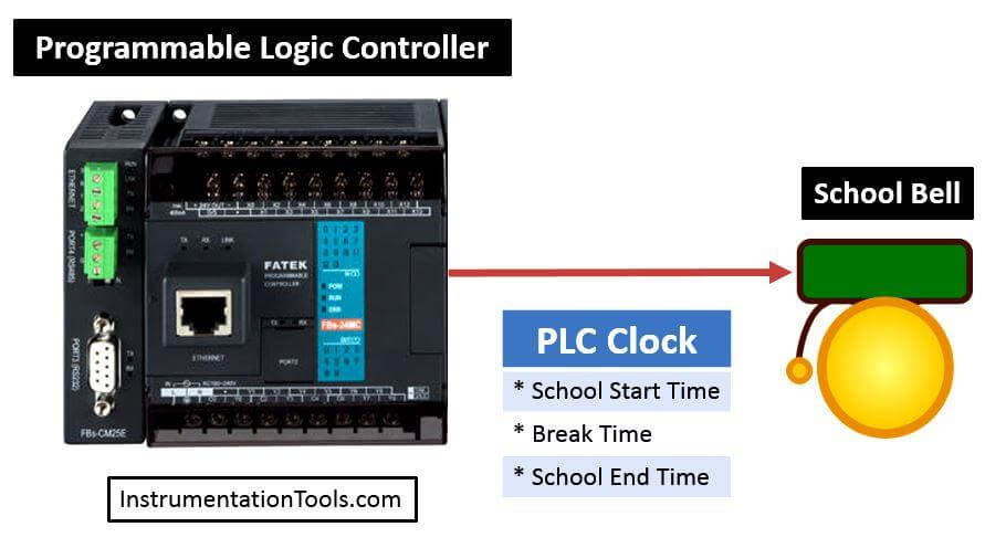
PLC based Automatic Bell System

Solution

For this automatic system we will use PLC programming. Here we read PLC time in the program and compare it.

For example in school we need to ring bell at three different time (School begin, breaks and end of the school.).

So compare this three different time using comparators. Also we will generate three different conditions for the bell output.

List of Inputs/Outputs

List of Outputs

  • Q0.0 :- School bell

M memory

  • M0.0 :- School begin bell ringing command
  • M0.1 :- Break time bell ringing
  • M0.2 :- School end bell ringing command
  • Internal tag 1 :- Actual time
  • Internal tag 2 :- School begin time
  • Internal tag 3 :- Break time
  • Internal tag 4:- School end time

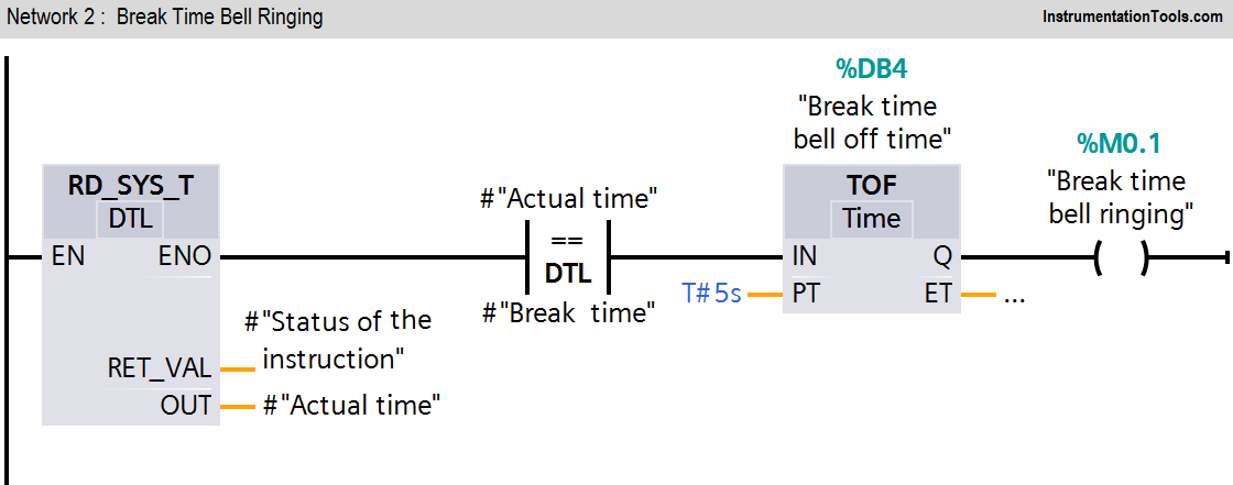
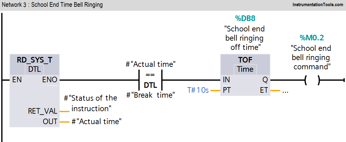
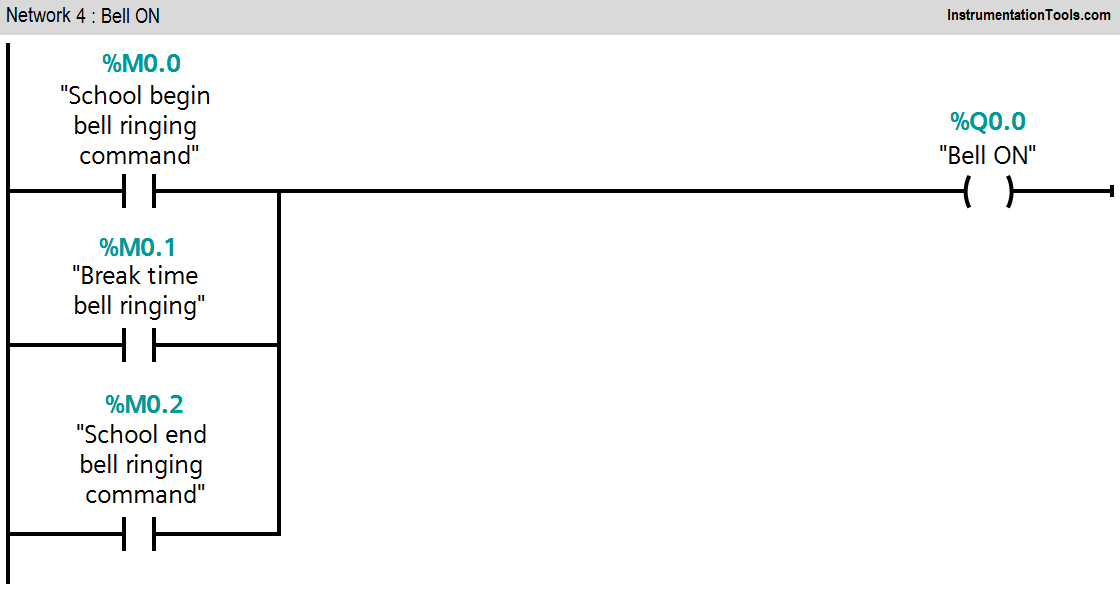
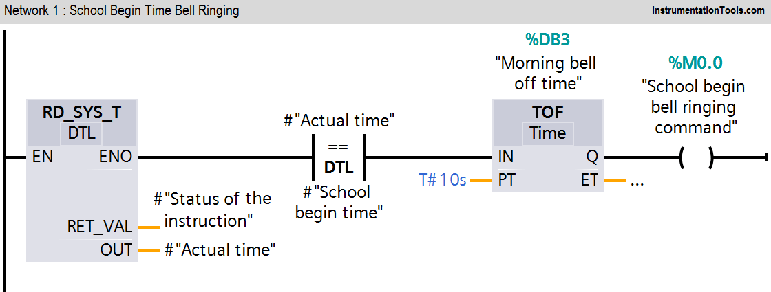
Ladder diagram for Automatic School Bell System
PLC Automatic Bell Logic
PLC Electric Bell Logic
PLC Ladder Logic for School Bell
PLC School Projects

Logic Description

Network 1 :-

Here School begin time is compared with actual time of the PLC clock. Bell condition will remain ON for 10s (seconds) and after 10s it will be OFF automatically.

Network 2 :-

Here School break time is compared with actual time of the PLC clock. Bell condition will remain ON for 5s and after 10s it will be OFF automatically.

Network 3 :-

Here School end time is compared with actual time of the PLC clock. Bell condition will remain ON for 10s and after 10s it will be OFF automatically.

Network 4 :-

Any condition out of three is triggered bell output will be ON.

Note :- Above application may be different from actual application. This example is only for explanation purpose only. We can implement this logic in other PLC also. This is the simple School bell control using PLC, we can use this concept in other examples also.

All parameters and graphical representations considered in this example are for explanation purpose only, parameters or representation may be different in actual applications. Also all interlocks are not considered in the application.

Author : Bhavesh

If you liked this article, then please subscribe to our YouTube Channel for PLC and SCADA video tutorials.

You can also follow us on Facebook and Twitter to receive daily updates.

Read Next:
Best 100 PLC Projects

Sensor Scaling + Offset

Quiz on PLC Systems

SCADA HMI Software

PLC Tank Mixing Logic

Don't Miss Our Updates
Be the first to get exclusive content straight to your email.
We promise not to spam you. You can unsubscribe at any time.
Invalid email address
You've successfully subscribed !

Continue Reading

PLC Program for Artificial Fishpond Water Level Monitoring System
Programmable Logic Controller Maintenance Check Points
PLC Ladder Logic for Sensor Scaling with Offset
PLC Important Questions and Answers
DeMorgan’s Theorems using Ladder Diagram
How to Create New Project Using Simatic Manager
Share This Article
Facebook Whatsapp Whatsapp LinkedIn Copy Link
Share
Leave a Comment

Leave a Reply Cancel reply

Your email address will not be published. Required fields are marked *

Stay Connected

128.3kFollowersLike
69.1kFollowersFollow
210kSubscribersSubscribe
38kFollowersFollow

Categories

Explore More

What is the DDE Protocol?
Value Assignments in SCL Language – Single, Multiple, Combined
Allen Bradley Powerflex VFD
Repeat Until Statement in SCL Language
Data Handling Instructions in PLC Programming
Electrical Earthing Calculations
PLC Programming Best Practices and Tips
PLC Ladder Logic Design: Control 3 Motors with Toggle Switch

Keep Learning

Functional block diagram for analog alarms

PLC Logic for Analog Alarms using Functional Block Diagram

SCADA Systems

SCADA Systems

Functional Block Diagram of XNOR Logic Gate

PLC Functional Block Diagram for Logic Gates

Factory Acceptance Test of PLC Panel

Factory Acceptance Test (FAT) of a PLC Panel

Free Omron PLC Programming Course in HINDI

Free Omron PLC Programming Course in HINDI

PLC Examples for calling functions in SCL

How to Insert Block Calls in SCL Language?

Siemens CP Module

Communication Processor Module in Siemens PLC

PLC Programming for Train Detection and Gate Operation

PLC Programming for Train Detection and Gate Operation

Learn More

trip solenoid installed on a control valve appears

SIS Final Control Elements

PLC Ladder Logic for Demultiplexer

1 to 8 Demultiplexer PLC ladder diagram

DC Motor Action

DC Motor Speed

Electric Motor Actuator Parts

Electric Motor Actuator Parts

What is an instruction list language?

Structured Text vs. Instruction List for PLC Programming

Logic Gates Symbols & Truthtables

Logic Gates Animation

Programmable Logic Controller Boiler Logic

PLC Ladder Logic for Start-up Control of Boilers

D flip flop in PLC

D Flip Flop PLC Ladder Logic

Menu

  • About
  • Privacy Policy
  • Copyright

Quick Links

  • Learn PLC
  • Helping Hand
  • Part Time Job

YouTube Subscribe

Follow US
All rights reserved. Reproduction in whole or in part without written permission is prohibited.
Welcome Back!

Sign in to your account

Username or Email Address
Password

Lost your password?