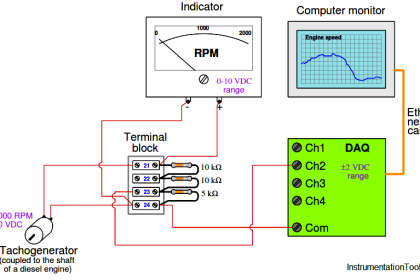
An ingenious circuit used to generate an electrical voltage signal from a differential capacitance pressure sensor is the Twin-T diode circuit, shown here connected to a Rosemount-style differential capacitance pressure sensor:
Pressure Sensor Circuit
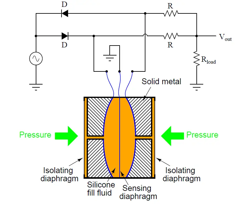
One capacitor is charged positive with respect to ground, while the other is charged negative with respect to ground, as the AC voltage source alternates positive and negative. While one capacitor of the pressure sensor is charging, the other is discharging through Rload, producing an output voltage (Vout).
If both capacitances are equal, the output voltage will alternate equally between positive and negative values, having a DC average value of zero. If one capacitance is larger than the other, it will store additional charge on its plates, causing it to sway the output voltage of the Twin-T circuit in the direction of its polarity. Thus, Vout becomes more positive as pressure increases on one side of the sensor, and more negative as pressure increases on the other side of the sensor.
Based on this explanation of the Twin-T circuit’s operation, determine which side of the pictured differential capacitance sensor is the “High” pressure side, and which is the “Low” pressure side. Be sure to explain your reasoning!
Share your answers with us through below comments section.
Read Next:
- Differential Pressure Gauge Principle
- Transmitter Circuit Voltage drop
- Hydraulic System Fluid Pressure
- Air Pressure Inside the Tank
- Question on Analytical Controller
Credits: Tony R. Kuphaldt


This is very interesting,I thank you so much!