Inst ToolsInst ToolsInst Tools
  • Courses
  • Automation
    • PLC
    • Control System
    • Safety System
    • Communication
    • Fire & Gas System
  • Instrumentation
    • Design
    • Pressure
    • Temperature
    • Flow
    • Level
    • Vibration
    • Analyzer
    • Control Valve
    • Switch
    • Calibration
    • Erection & Commissioning
  • Interview
    • Instrumentation
    • Electrical
    • Electronics
    • Practical
  • Q&A
    • Instrumentation
    • Control System
    • Electrical
    • Electronics
    • Analog Electronics
    • Digital Electronics
    • Power Electronics
    • Microprocessor
  • Request
Search
  • Books
  • Software
  • Projects
  • Process
  • Tools
  • Basics
  • Formula
  • Power Plant
  • Root Cause Analysis
  • Electrical Basics
  • Animation
  • Standards
  • 4-20 mA Course
  • Siemens PLC Course
Reading: Open Channel Flow Measurement Principle
Share
Font ResizerAa
Inst ToolsInst Tools
Font ResizerAa
  • Courses
  • Design
  • PLC
  • Interview
  • Control System
Search
  • Courses
  • Automation
    • PLC
    • Control System
    • Safety System
    • Communication
    • Fire & Gas System
  • Instrumentation
    • Design
    • Pressure
    • Temperature
    • Flow
    • Level
    • Vibration
    • Analyzer
    • Control Valve
    • Switch
    • Calibration
    • Erection & Commissioning
  • Interview
    • Instrumentation
    • Electrical
    • Electronics
    • Practical
  • Q&A
    • Instrumentation
    • Control System
    • Electrical
    • Electronics
    • Analog Electronics
    • Digital Electronics
    • Power Electronics
    • Microprocessor
  • Request
Follow US
All rights reserved. Reproduction in whole or in part without written permission is prohibited.
Inst Tools > Blog > Animation > Open Channel Flow Measurement Principle

Open Channel Flow Measurement Principle

The open channel flow measurement principle is to measure the height or head of the liquid as it passes over an obstruction.

Last updated: November 1, 2023 11:35 am
Editorial Staff
Animation Flow Measurement
4 Comments
Share
1 Min Read
SHARE

The common method of measuring flow through an open channel is to measure the height or HEAD of the liquid as it passes over an obstruction (a flume or weir) in the channel.

Using ultrasonic level technology, Open channel flow meters include a non-contacting sensor mounted above the flume or weir.

By measuring the time from transmission of an ultrasonic pulse to receipt of an echo, the water level or “Head” is accurately measured.

Open Channel Flow Measurement
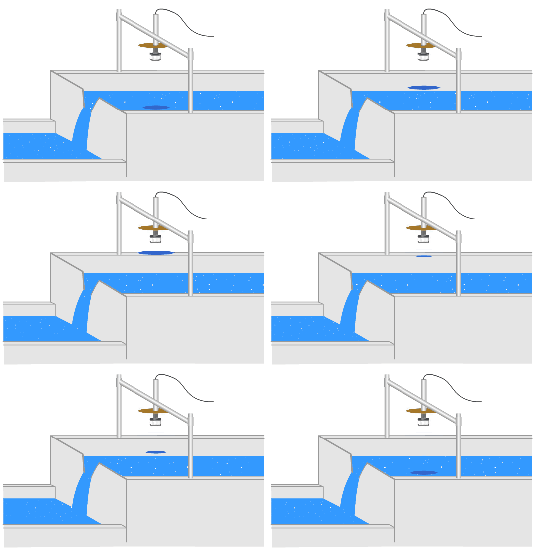
Open Channel Flow Measurement Animation

Animation Credits: greyline

Flumes and weirs are specially designed channel shapes that characterize the flow of water.

Common types are

  • Rectangular Weirs,
  • V-Notch Weirs,
  • Parshall flumes and
  • Palmer Bowlus flumes.

The choice of flume or weir type depends on the application: flow rate, channel shape, and solids content of the water.

If you liked this article, then please subscribe to our YouTube Channel for Instrumentation, Electrical, PLC, and SCADA video tutorials.

You can also follow us on Facebook and Twitter to receive daily updates.

Read Next:

  • Instrument Tube Bending
  • Flow Meter Installation Guide
  • Temperature Sensor Accessories
  • How Weigh Feeder Works?
  • Valve Materials Comparison
Don't Miss Our Updates
Be the first to get exclusive content straight to your email.
We promise not to spam you. You can unsubscribe at any time.
Invalid email address
You've successfully subscribed !

Continue Reading

Oval Gear Flow Meters – Principle, Advantages, Animation
Impulse Line – Purpose & Tapping Point Location
Encoder Working Principle
Capacitance Level Transmitter Animation
Flow Nozzle Principle, Advantages, Disadvantages, Applications
Turbine Flow Meters Troubleshooting
Share This Article
Facebook Whatsapp Whatsapp LinkedIn Copy Link
Share
4 Comments
  • hardik bodar says:
    August 25, 2018 at 6:31 pm

    how to calculate open channel flow from parshall flume data ?

    Reply
    • Jatin Katrodiya says:
      January 22, 2021 at 12:01 am

      Normally in power plant, this type of arrangement is installed. River/reservoir water coming to plant is measured.

      Flow measurement through parshall flume depends on flume geometry (e.g converging, diverging and throat section : height, slop and length)

      Q = C*H^n

      Where
      Q is flow rate
      C is the free-flow coefficient
      H is the head at throat section
      n varies with flume size

      Reply
  • MJ Cabugsa says:
    December 7, 2018 at 8:33 am

    Good day! We are working on a project study that will prove Bernoulli’s Principle. Do we need to place two ultrasonic level sensors before and after it passes the weir? Where is the right place of the sensor for the second weir?

    Reply
  • Ramzi says:
    October 18, 2024 at 7:53 am

    Many thanks for this valuable information 👍

    Reply

Leave a Reply Cancel reply

Your email address will not be published. Required fields are marked *

Stay Connected

128.3kFollowersLike
69.1kFollowersFollow
210kSubscribersSubscribe
38kFollowersFollow

Categories

Explore More

Area Velocity Flow Meter Principle
What is ON/OFF Valve ?
Configure the Instruments in Flow Control Loop
Motor Classic Control Circuits using Single Push button
Ultrasonic Doppler Flow Meter Advantages and Disadvantages
Read Gas Composition from Gas Metering System using RS485 Protocol
Pressure Transmitter Animation
DP Flow Transmitter Re-Ranging Calculation

Keep Learning

Flow Transmitters Questions and Answers

Flow Transmitters Questions and Answers – Instruments Test

Coriolis Mass Flow meter as a Multi Variable Transmitter - 2

Coriolis Flowmeter Advantages and Limitations

Coriolis Flow Meter Inaccuracy

Coriolis Flow Meter Uncertainty and Inaccuracy

Averaging Pitot Tubes

Pitot Tube Problems and Troubleshooting Steps – Flow Instrument

Proximity Switch PNP Type Working Animation

Proximity switches Circuit Diagram Operation

How a Δp flow meters works

What is Differential Pressure Flow Meter?

Sick Flow meters

Flare Ultrasonic Flow Meter – SOPAS Engineering Tool

Annubar flow principle

Different Types of Flow Elements

Learn More

PLC Stop - Start Circuit

Introduction to PLC Ladder Diagrams

Field Instruments Questions and Answers

Basics of Amplifiers Interview Questions

VPN for Control Engineers

How Important is VPN for Control Engineers?

PLC DIN Rail

What is DIN rail ?

Timer STL Programming

Timers using Statement List (STL) PLC Programming

Override Control Functions

Override Control Functions

List of 100 Sensors and Transducers Questions

List of 100 Sensors and Transducers Questions

How to Select a Inductive Proximity Sensor

How to Select a Inductive Proximity Sensor

Menu

  • About
  • Privacy Policy
  • Copyright

Quick Links

  • Learn PLC
  • Helping Hand
  • Part Time Job

YouTube Subscribe

Follow US
All rights reserved. Reproduction in whole or in part without written permission is prohibited.
Welcome Back!

Sign in to your account

Username or Email Address
Password

Lost your password?