What is a common Base amplifier?
Common base amplifier is on in which the base terminal is common to both input and output circuit. Following are the some of the characteristic parameters of CB amplifier neglecting the output resistance of amplifier (which accounts for early effect) are
Rin = re
Av = gm*(Rc//Rl)
Rout = Rc
Gv = α*(Rc//Rl)/(Rsig+re)
Ais = α.
What is a Common emitter amplifier?
Common emitter amplifier is on in which the emitter terminal is common to both input and output circuit. Following are the some of the characteristic amplifiers of CE amplifier with emitter resistance neglecting the output resistance of amplifier (which accounts for early effect) are
Rin = Rb//(β+1)*(re+Re)
Av = -gm*(Rc//Rl)/(1+gm*Re)
Rout = Rc
Gv = -β*(Rc//Rl) / (Rsig+(β+1)*(re+Re))
Ais = -α*( Rb//(β+1)*(re+Re))/(re+Re).
What is a Common collector amplifier?
Common collector amplifier is on in which the collector terminal is common to both input and output circuit. Following are the some of the characteristic amplifiers of CC amplifier are
Rin = Rb//(β+1)*(re+(ro//Rl))
Av = (ro//Rl)/( ro//Rl+re)
Rout = ro//(re+(Rsig//Rb/(β+1)))
Gv = (Rb/(Rb+Rsig))*( ro//Rl/(Rsig//Rb/(β+1))+re+(ro//Rl)))
Ais = β+1.
What are the applications of transistor amplifiers?
a) The CE amplifiers are used in applications where high gain is required. It can be used as single stage or in cascade.
a) CB amplifiers have better frequency response than CE amplifier. It is used as high frequency amplifier combined with common emitter amplifier. Its low input resistance finds application in specific areas where the signal strengths are very low (or) when load on source should be very low.
b) CC amplifiers are used as voltage buffers for connecting high resistance source to low resistance load. It is used as output stage in multistage amplifier because of its low output resistance.
What is Darlington pair?
Darlington pair consists of two cascaded emitter followers used to achieve high input resistance. Darlington pair is a better buffer compared to single stage emitter follower circuit. The typical Darlington pair is shown below

Following are some of the characteristic parameters of Darlington pair
Rin = (1+β)^2 *Re/(1+β*Re/ro)
Ai = (1+β)^2/(1+ β*Re/ro)
Av = 1-β*(2+β*Re/ro)/((1+β)*Re)
Ro = Rsig/(1+β)^2+(2*β)/(1+β)
What is cascade amplifier?
To meet given amplifier specifications two or more stages are cascaded in series, each stage can be identical or different. Such amplifiers are called cascade amplifiers. Often amplifier with common emitter multi stages is referred to as Cascade amplifier.
Explain cascade amplifier?
Cascade amplifier is a Common base amplifier stage in cascade with common emitter stage. It combines the high resistance, large Transconductance (high gain) achieved in common emitter amplifier with the superior high frequency response of common base amplifier. It is designed to achieve wider bandwidth but dc gain approximately equal o that of common emitter amplifier.
What are interacting and non-interacting cascading stages?
If in a cascade of stages the input impedance of one stage is low enough to act as an appreciable shunt on the output impedance of the preceding stage the output impedance of the preceding stage the stages are said to interacting stages.
If in a cascade of stages the input impedance of one stage is high enough so that it will not be able to affect the output impedance of the preceding stage the stages are said to Non-interacting stages.
What is lower/upper cut-off frequency of non-interacting cascading stages?
For n Non-interacting stages with each stage having lower and upper cut-off frequencies as fl, fh the upper and lower cut-off frequencies are given as follows
fh” = fh*(2^(1/n)-1)^(1/2)
fl” = fl/(2^(1/n)-1)^(1/2)
What is the upper cut-off for interacting stages?
The upper cut-off frequency of n interacting stages with each stage having upper cut-off frequencies fh is
1/fh” = 1.1*((1/f1^2)+(1/f2^2)+……..+(1/fn^2))^(1/2)
Why amplifier gains will reduce at higher frequency?
At high frequencies internal feedback capacitance’s comes into picture. These capacitance’s introduce negative feedback from output to input which reduces the amplifier gain at high frequencies.
What are the types of coupling used in amplifiers?
The term Coupling occurs in multi stage amplifiers and refers to the way in which the output of one stage is connected to the input of next stage. There are mainly three types of coupling which are
- Transformer coupling
- Capacitive coupling
- DC coupling
- Opto coupling
What is direct coupling?
A direct coupling is one in which the output of one stage of amplifier is connected to the input of second stage in such a way to allow even DC signals from one stage to another. The frequency response of the direct coupled amplifier is similar to low pass filter and is characterized by rise time.
The main disadvantage with DC coupling is, since there is no DC isolation the first stage acts as a biasing circuitry for the second stage, the AC signal current is superimposed on DC quiescent currents and this effect propagates.
What is capacitive coupling?
A capacitive coupling is one in which the output of one stage of amplifier is connected to the input of second stage through a capacitor. This is the most frequently used coupling. The coupling capacitor blocks DC signal propagation across the amplifier and allows only AC signals. This makes the circuit analysis and design simplified and each stage can be considered as isolated as far as DC signals are considered. Also it avoids the amplifiers going into DC saturation.
What is transformer coupling amplifier?
A Transformer coupling is one in which the output stage of one amplifier is coupled to the input stage of next amplifier through a transformer. By choosing the appropriate turns ratio a transformer can be used to provide impedance matching with the load. If N1, N2 and Z1,Z2 are the turns ration and impedance of primary and secondary coil of the transformer then the primary coil impedance and secondary coil impedance are related as Z2 = Z1*(N2/N1)^2. Such coupling is used in high frequency amplification. Introduction of Transformer makes the amplifier bulkier and costly.
What is miller’s theorem?
The Miller’s theorem establishes that in a linear circuit, if there exists a branch with impedance Z, connecting two nodes with nodal voltages V1 and V2, we can replace this branch by two branches connecting corresponding nodes to ground by impedances Z/(1-K) and K*Z/(K-1) where K = V2/V1. It is shown in the figure below

Give differential amplifier using BJT, FET?
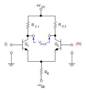
Differential amplifier BJT
A differential amplifier provides high gain for differential input signals and low gain for common mode signals. Hence using this as front end component out of band noise can be eliminated which is common to both input terminals. The differential amplifier implemented using BJT’s are shown below
 Differential amplifier MOSFET
The resistance in the emitter lead plays a crucial role in the functioning of differential amplifier. This resistance has to be high in order that the CMMR of differential amplifier to be high. Alternatively in the improvised versions of differential amplifiers a constant current source is kept in emitter lead to provide very high resistance (Theoretically infinite). The same differential amplifiers implemented using MOSFET’s is shown below
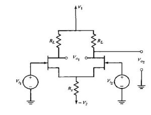
The MOSFET differential amplifier provides high input resistance but less gain compared to differential amplifiers implemented using BJT’s.
What is CMMR of differential amplifier using BJT? What is the effect of degeneration resistance on CMMR?
The CMMR of differential amplifier using BJT with emitter resistance at the common terminal where the emitters of both the BJT’s meet and output taken across the collector terminals is given as
CMMR = |Ad/Ac| = gm*Re
where Ad (differential gain) = -gm*Rc, Acm (common mode gain of each stage)= -Rc/(2*Re) and the overall common mode gain of differential amplifier will be double of Acm.
It is obvious from the expression of CMMR that increase in emitter degeneration resistance increases CMMR.
What is feedback amplifier?
If a amplifier has feedback path exists from output to input then that amplifier is termed as Feedback amplifier. Feed back is the parameter which quantifies the amount of feedback given in a feedback amplifier. Feedback factor = Feedback signal/input signal.
What is negative and positive feedback?
If feedback from output to input is given in such in a way that the introduction of feedback in the amplifier decreases the overall gain, then the feedback is termed as negative feedback.
If feedback from output to input is given in such in a way that the introduction of feedback in the amplifier increases the overall gain, then the feedback is termed as positive feedback.
What are Advantages and disadvantages of Negative feedback?
Some of the Advantages of negative feedback:
a) Input resistance increases
b) Output resistance decreases
c) Bandwidth increases
d) Non linear distortion decreases
e) Frequency distortion decreases
f) Sensitivity will be decreased
g) Gain stability
The main disadvantage of negative feedback is decrease in overall gain. The gain and feedback factor in an amplifier are often functions of frequency, so the feedback may lead to positive feedback.
What is de-sensitivity factor?
Desensitivity factor is defined as the factor with which the feedback desensitizes the gain. It is also called as return difference.
Desensitivity factor = (dAfb/Afb)/(dA/A) = 1/(1+A*β)
Where Afb is gain with feedback
A is gain without feedback
β is feedback factor.
What is a loop gain in amplifier?
Loop gain in amplifier is defined as the gain of feedback path from output to input. It is the product of loop gain and feedback factor in positive feedback amplifiers. In negative feedback amplifiers it is the negative product of loop gain and feedback factor.


Dear sir,
kindly tell ,how to save the document.
Hi, You can find print option at the bottom of the article. use it to save in pdf.