Have you ever visited an unknown place? If yes, then I am sure that you must have followed this way.
Go to Country → State → City → Local Area → then place to be visited.
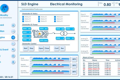
When you have a process plant wherein the control system has I/Os in the range of thousands, it is very difficult to identify their exact location especially when you need to do some troubleshooting.
Nest Loading
Nest loading is the overall footprint of all the inputs and outputs of the control system (PLC, DCS, etc). Nest loading in simple terms means I/O Assignment or I/O allocation.
Every I/O channel in the control system has unique addresses. These addresses are assigned in a specific format as mentioned below. The nest loading document covers these details for each tag number wired to the control system.
Domain No → Station No → Node No/Rack No → Slot No → Channel No.
For example,
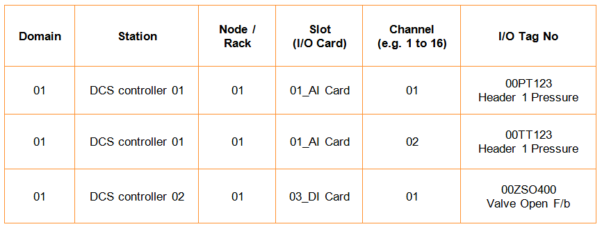
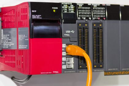
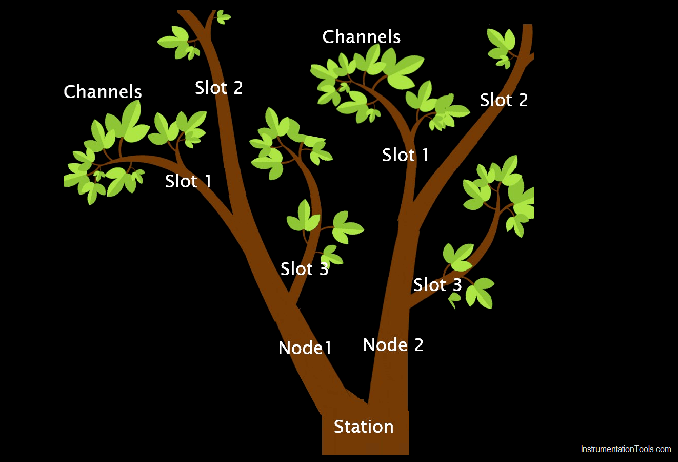
Depending upon controller capability, the number of nodes and slots can be connected. Each slot means the I/O module itself. I/O modules have their channels depending upon the type.
For example 8 channel AI module or 4 channel AO module or 16 channel DI module.
Each tag number can be assigned to an individual I/O channel. Hence the I/O address is unique for each tag number. This can be illustrated with the following figure for better clarity.
Best Practices for Nest Loading
The below are the some of the best practices for the I/O Assignment or I/O Allocation
1) All the tag numbers should be covered as per system-wise database e.g. DCS, ESD, FGS, PLC, etc
SIL rated I/O modules and controller are different than non-SIL rated. I/O module model no should be checked for DCS and ESD.
2) System diagnostic alarms such as Fan failure alarm, Power supply module failure, Temperature high, Earth leak detected or common alarm should be included in Nest loading. Sometimes I/O List document is prepared without these diagnostic I/Os.
3) Redundancy requirement of I/Os should be properly checked. e.g. Critical close-loop I/Os of DCS system shall be redundant, ESD & FGS I/Os shall be redundant. Redundant modules shall be installed and configured for redundant I/Os.
4) I/O allocation should be based on the Controller segregation philosophy. Sometimes controller for utility (like IA compressors, chemical dosing systems, drainage system, etc) and controller for the main process is different so that I/O assignment should be reviewed in a view of same that utility package related I/Os should not be connected to Process controller I/O modules and vise versa.
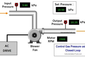
5) Closed-loop I/Os (i.e. Analog input and Analog Output) should be assigned in one I/O module.
6) 2oo3 / 1oo2 / 2oo2 Voting I/Os should be allocated in different I/O modules.
7) F&G detector I/Os which are part of 2ooN should be allocated in different I/O modules.
8) Main and standby equipment (parallel equipment’s) related I/Os should be assigned in different I/O cards (Pump A, Compressor A related I/Os can be combined but Pump A and Pump B related I/Os should not be assigned in one module). Also LT and HT motors related I/Os should not be considered in One I/O module.
9) MCC related I/Os and Process/utility related I/Os should not be mixed in one I/O card.
The reason for having Sr no 5,6,7,8,9 is to avoid a single point of failure should not impact more than one instrument/equipment or process.
10) Relay location is important for I/Os identified as DO with Relay output. (Relay at Marshalling panel or separate cabinet such as IRP cabinet). Sometimes relay adaptor is part of the I/O Module (e.g Yokogawa‘s NIO based A2MMM843 Card with A2SDV505 or A2SDV506) adaptors. These relay adapters/relay boards should be cross-checked in Panel GA/IA drawings.
11) Multiple I/O channels (for delivering higher current) or Wetted relay output can be considered for Digital Output signals identified as high powered 24V DC instruments such as solenoids, sounders, beacons, etc. Agreed philosophy should be followed.
12) Hardwired I/Os should not be considered between DCS and ESD if these systems are on an integrated network. E.g. ESD DO to DCS input. It should be considered when the different make of DCS and ESD systems is installed.
13) Some clients do not prefer to mix all types of I/O in One Universal I/O module (As universal I/O module can be used for AI, AO, DI, DO those I/Os can be mixed in one I/O card). Non-mixing can result in higher I/O modules and related wired spares etc
14) Wired Spare (installed spare) related I/Os and their tag assignment philosophy should be as per the Client‘s requirement.
15) When using electronic marshaling where field cables are connected directly on the I/O module (not on terminal blocks), the number of main cables terminated in one cabinet should be reviewed properly for ease of maintenance.
16) When you have remote I/O (RIO) panels then I/Os related to that area should be assigned in that particular Rack and slots of RIO. Otherwise, you will end up with a higher length of main cables from the field to the Control system.
17) The Rack no/ Node no, slot no. and module no. indicated on the nest loading document should be cross-checked with the system GA drawing.
18) Quantity of I/O modules and Spare space (for future I/O installation) should be cross-checked with the system GA drawing.
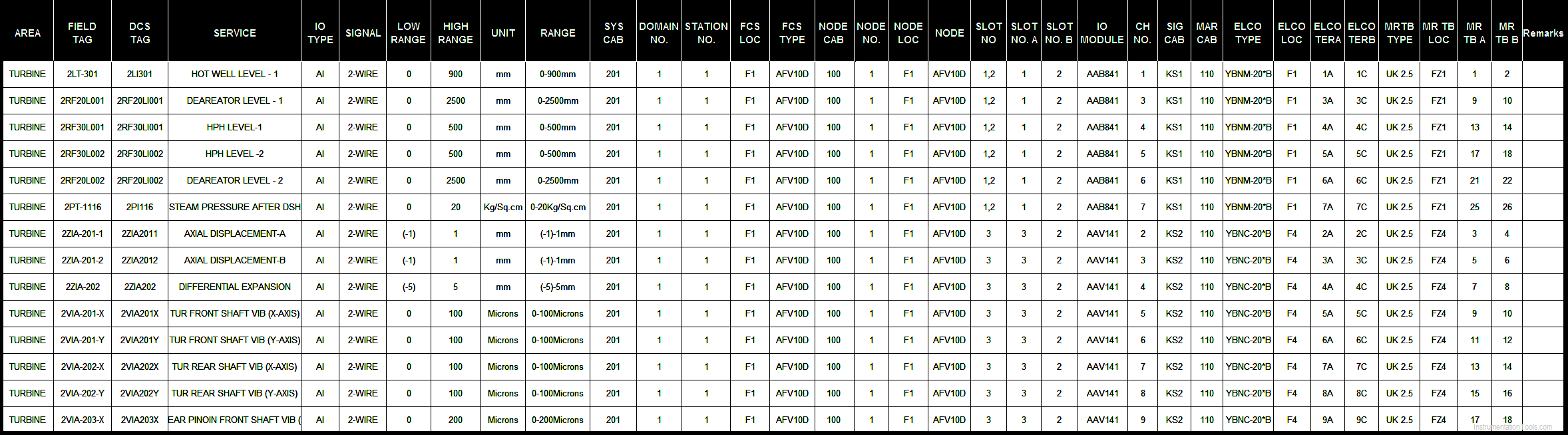
Example Nest Loading List
Author: Jatin Katrodiya
If you liked this article, then please subscribe to our YouTube Channel for PLC and SCADA video tutorials.
You can also follow us on Facebook and Twitter to receive daily updates.
Read Next:
- UPS Selection Factors
- Flow Compensation
- DCS System Architecture
- Wiring Diagrams of PLC
- Interposing Relay Panel