Inst ToolsInst ToolsInst Tools
  • Courses
  • Automation
    • PLC
    • Control System
    • Safety System
    • Communication
    • Fire & Gas System
  • Instrumentation
    • Design
    • Pressure
    • Temperature
    • Flow
    • Level
    • Vibration
    • Analyzer
    • Control Valve
    • Switch
    • Calibration
    • Erection & Commissioning
  • Interview
    • Instrumentation
    • Electrical
    • Electronics
    • Practical
  • Q&A
    • Instrumentation
    • Control System
    • Electrical
    • Electronics
    • Analog Electronics
    • Digital Electronics
    • Power Electronics
    • Microprocessor
  • Request
Search
  • Books
  • Software
  • Projects
  • Process
  • Tools
  • Basics
  • Formula
  • Power Plant
  • Root Cause Analysis
  • Electrical Basics
  • Animation
  • Standards
  • 4-20 mA Course
  • Siemens PLC Course
Reading: Pressure Transmitter Calibration Procedure
Share
Notification Show More
Font ResizerAa
Inst ToolsInst Tools
Font ResizerAa
  • Courses
  • Design
  • PLC
  • Interview
  • Control System
Search
  • Courses
  • Automation
    • PLC
    • Control System
    • Safety System
    • Communication
    • Fire & Gas System
  • Instrumentation
    • Design
    • Pressure
    • Temperature
    • Flow
    • Level
    • Vibration
    • Analyzer
    • Control Valve
    • Switch
    • Calibration
    • Erection & Commissioning
  • Interview
    • Instrumentation
    • Electrical
    • Electronics
    • Practical
  • Q&A
    • Instrumentation
    • Control System
    • Electrical
    • Electronics
    • Analog Electronics
    • Digital Electronics
    • Power Electronics
    • Microprocessor
  • Request
Follow US
All rights reserved. Reproduction in whole or in part without written permission is prohibited.
Inst Tools > Blog > Calibration > Pressure Transmitter Calibration Procedure

Pressure Transmitter Calibration Procedure

Last updated: May 30, 2019 3:21 pm
Editorial Staff
Calibration Pressure Measurement
No Comments
Share
3 Min Read
SHARE

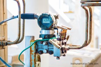
This article provides step-by-step Procedure for Pressure Transmitter Calibration and Ranging, LRV and URV configuration of transmitter.

Pressure Transmitter Details :

  • Rosemount Make, 3051 series
  • 3051T- Guage & absolute pressure (models) 0.3 to 10000psi, 10.3 mbar to 689 bar
  • 3051C, DP guage & absolute (models) 0.1 to H2o to 4000psi, 0.25 mbar to 276 bar
  • Power supply range is 12VDC to 32VDC.

Pressure Transmitter Calibration Procedure

Main Steps to be Followed :

First step to be followed is proper permit should be taken and ensure the interlocks should be by passed as well as MOS (Maintenance override to be put ON condition in DCS) for the particular tag.

Use Tool box meeting & proper PPE’S .

Required tools and suitable fittings (Such as connector and union) for calibration.

Multimeter, HART communicator, Calibrator ( Pressure range should be greater than the transmitter)

For higher range use hydraulic pressure calibrators and for low ranges use low range calibrator.

Calibration Procedure

  1. First isolate the main process isolation valve.
  2. De-pressurize the pressure transmitter by opening the vent valve
  3. Isolate the manifold valve and open the vent plug.
  4. Fix proper instrument fitting ( for eg:1/4”npt fitting)
  5. Connect the calibrator fitting in to the vent plug entry of manifold valve.
  6. The vent valve should be opened.
  7. The HART communicator cable should be placed as per transmitter wiring diagram.
  8. Apply pressure as per the range given in the transmitter or check with the HART communicator.
  9. Check the transmitter reading by applying pressure for 25%, 50%, 75%, and span range.
  10. If the transmitter needs to be calibrated use the HART communicator for calibration purpose.
  11. Zero & span trims can be done by using HART communicator.
  12. After calibration checking remove the pressure calibrator from the transmitter and flush the line.
  13. So that hydraulic oil or water will not be inside the transmitter.
  14. Close the vent plug.
  15. Isolate the vent valve and open the main isolation valve.
  16. Open the manifold isolation valve slowly, if u open fast sudden pressure may damage the transmitter diaphragm.
  17. After completion of the calibration ensure the transmitter is reading showing properly.
  18. Then enter the reading in calibration  report format.
  19. Check the reading in DCS also.
  20. Close the work permit from field operator and shift Engineer.

Articles You May Like :

Pressure Transmitter Manifolds

Differential Pressure Transmitters

Displacer Level Transmitter Calibration
4–20 mA Process Control Loops

HART Communication Guide

Don't Miss Our Updates
Be the first to get exclusive content straight to your email.
We promise not to spam you. You can unsubscribe at any time.
Invalid email address
You've successfully subscribed !

Continue Reading

Troubleshooting Fluid Systems Pressure Changes
Open Tank DP Level Transmitter Calibration
Pressure Gauges : Common Causes for Failures and Their Effective Solutions
Pressure Gauge Installation at Pump Discharge
What is a Dead Weight Tester?
Conductivity Transmitter Calibration Procedure
Share This Article
Facebook Whatsapp Whatsapp LinkedIn Copy Link
Share
Leave a Comment

Leave a Reply Cancel reply

Your email address will not be published. Required fields are marked *

Stay Connected

128.3kFollowersLike
69.1kFollowersFollow
210kSubscribersSubscribe
38kFollowersFollow

Categories

Explore More

What is a Submersible Pressure Transmitter? Principle, Advantages
Instrument Zero and Span Calibration
Bellows, Diaphragms and Bourdon Tubes
Impulse Line Pressure Testing Procedure
Methods of Measurement
Functions of Pressure Detectors
Difference between Accuracy and Precision
What is Reliability Centered Maintenance? (RCM)

Keep Learning

Technologies for Oxygen Gas Measurement

How to Calibrate Oxygen Analyzer? – O2 Sensor Testing Procedure

Barometer Principle

What is a Barometer?

Pressure Gauge with Syphons

Pressure Gauge Syphons Principle

diaphragm-pressure-gauge

Diaphragm Pressure Sensors

Differential Pressure Sensor for Filtration Monitoring

Differential Pressure Sensor for Filtration Monitoring

Difference between Accuracy, Tolerance, Uncertainty, and Error

Difference between Accuracy, Tolerance, Uncertainty, and Error

Pressure Transmitter Working Principle

Gage and Absolute Pressure Transmitters Principle

Pressure Switch Construction

Basics of Pressure switches

Learn More

Impulse Line Problems

What are Impulse Lines? – Impulse Line Problems & Solutions

Electrical Machines Questions and Answers

Energy Conversion Quiz

Hydrostatic Level Measurement

Hydrostatic Level Measurement

Types of Pressure Measuring Scales

Types of Pressure Measuring Scales

Rotary Encoder

Rotary Encoder Interview Questions and Answers

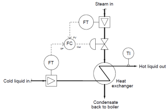
Heat Exchanger Outlet Temperature Control

Heat Exchanger Temperature Control

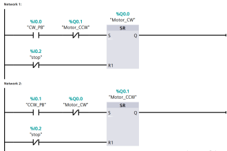
Motor Stop Interlock for Changing the Direction PLC Program

Motor Stop Interlock for Changing the Direction PLC Program

Programmable Logic Controller Quiz

Programmable Logic Controller Quiz

Menu

  • About
  • Privacy Policy
  • Copyright

Quick Links

  • Learn PLC
  • Helping Hand
  • Part Time Job

YouTube Subscribe

Follow US
All rights reserved. Reproduction in whole or in part without written permission is prohibited.
Welcome Back!

Sign in to your account

Username or Email Address
Password

Lost your password?