To better understand the design and operation of self-balancing pneumatic mechanisms, it is helpful to examine the workings of some actual instruments.
In this section, we will explore three different pneumatic instruments: the Foxboro model 13A differential pressure transmitter, the Foxboro model E69 I/P (electro-pneumatic) transducer, the Fisher model 546 I/P (electro-pneumatic) transducer, and the Fisher-Rosemount model 846 I/P (electro-pneumatic) transducer.
Foxboro model 13A differential pressure transmitter
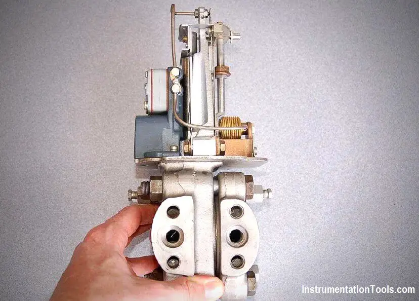
Perhaps one of the most popular pneumatic industrial instruments ever manufactured is the Foxboro model 13 differential pressure transmitter.
A photograph of one with the cover removed is shown here:
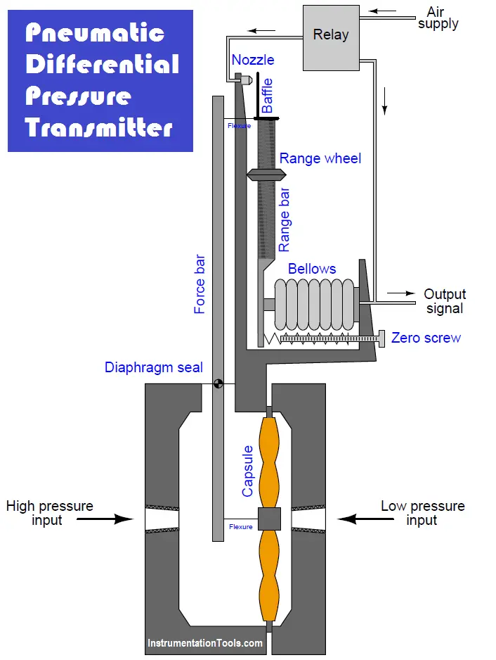
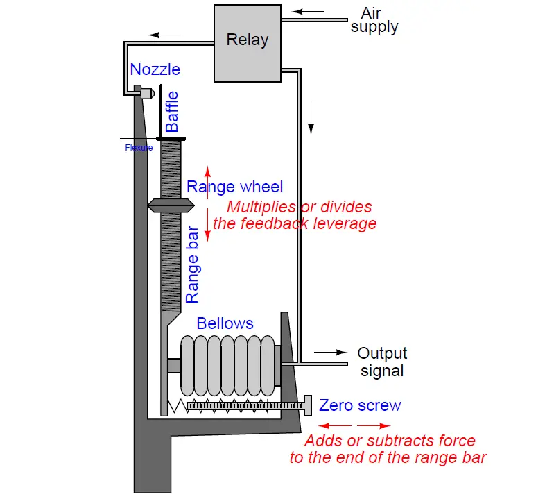
A functional illustration of this instrument identifies its major components:
Part of the reason for this instrument’s popularity is the extreme utility of differential pressure transmitters in general.
A “DP cell” may be used to measure pressure, vacuum, pressure differential, liquid level, liquid or gas flow, and even liquid density.
A reason for this particular differential transmitter’s popularity is its excellent design: the Foxboro model 13 transmitter is rugged, easy to calibrate, and quite accurate.
Like so many pneumatic instruments, the model 13 transmitter uses the force-balance (more precisely, the moment-balance) principle whereby any shift in position is sensed by a detector (the baffle/nozzle assembly) and immediately corrected through negative feedback to restore equilibrium.
As a result, the output air pressure signal becomes an analogue of the differential process fluid pressure sensed by the diaphragm capsule.
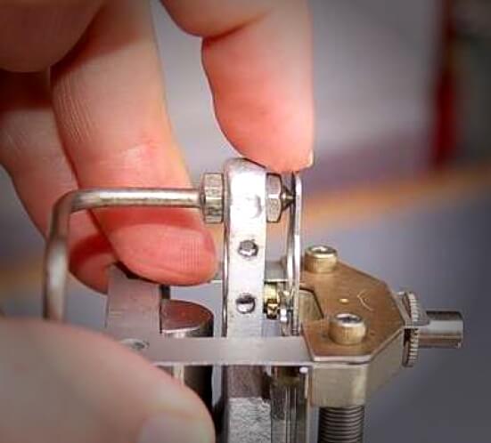
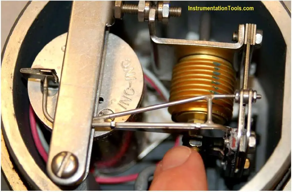
In the following photograph you can see my index finger pointing to the baffle/nozzle mechanism at the top of the transmitter:
Let’s analyze the behavior of this transmitter step-by-step as it senses an increasing pressure on the “High pressure” input port. As the pressure here increases, the large diaphragm capsule is forced to the right.
The same effect would occur if the pressure on the “Low pressure” input port were to decrease.
This is a differential pressure transmitter, meaning it responds to fluid pressure differences sensed between the two input ports.
This resultant motion of the capsule tugs on the thin flexure connecting it to the force bar. The force bar pivots at the fulcrum (where the small diaphragm seal is located) in a counter-clockwise rotation, tugging the flexure at the top of the force bar.
This motion causes the range bar to also pivot at its fulcrum (the sharp-edged “range wheel”), moving the baffle closer to the nozzle.
As the baffle approaches the nozzle, air flow through the nozzle becomes more restricted, accumulating backpressure in the nozzle.
This backpressure increase is greatly amplified in the relay, sending an increasing air pressure signal both to the output line and to the bellows at the bottom of the range bar.
Increasing pneumatic pressure in the bellows causes it to push harder on the bottom of the range bar, negating the initial motion (Note) and returning the range bar (and force bar) to their near-original positions.
Note : This negating action is a hallmark of force-balance systems. When the system has reached a point of equilibrium, the components will have returned to (very nearly) their original positions. With motion-balance systems, this is not the case: one component moves, and then another component moves in response to keep the baffle/nozzle detector at a near-constant gap, but the components definitely do not return to their original positions or orientations.
Calibration of this instrument is accomplished through two adjustments: the zero screw and the range wheel. The zero screw simply adds tension to the bottom of the range bar, pulling it in such a direction as to further oppose the bellows’ force as the zero screw is turned clockwise.
This action attempts to push the baffle closer to the nozzle and therefore increases air pressure to the bellows to achieve equilibrium.
Turning the range wheel alters the lever ratio of the range bar, changing the ratio of capsule force to bellows force and thereby adjusting the transmitter’s span.
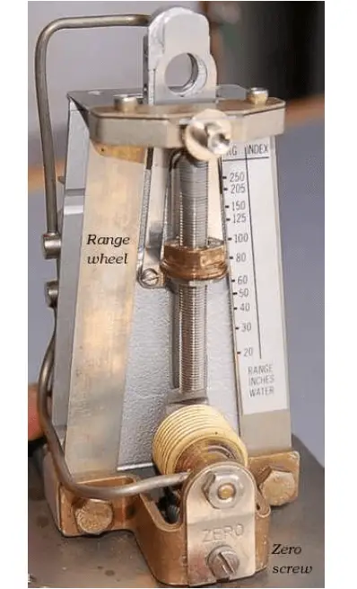
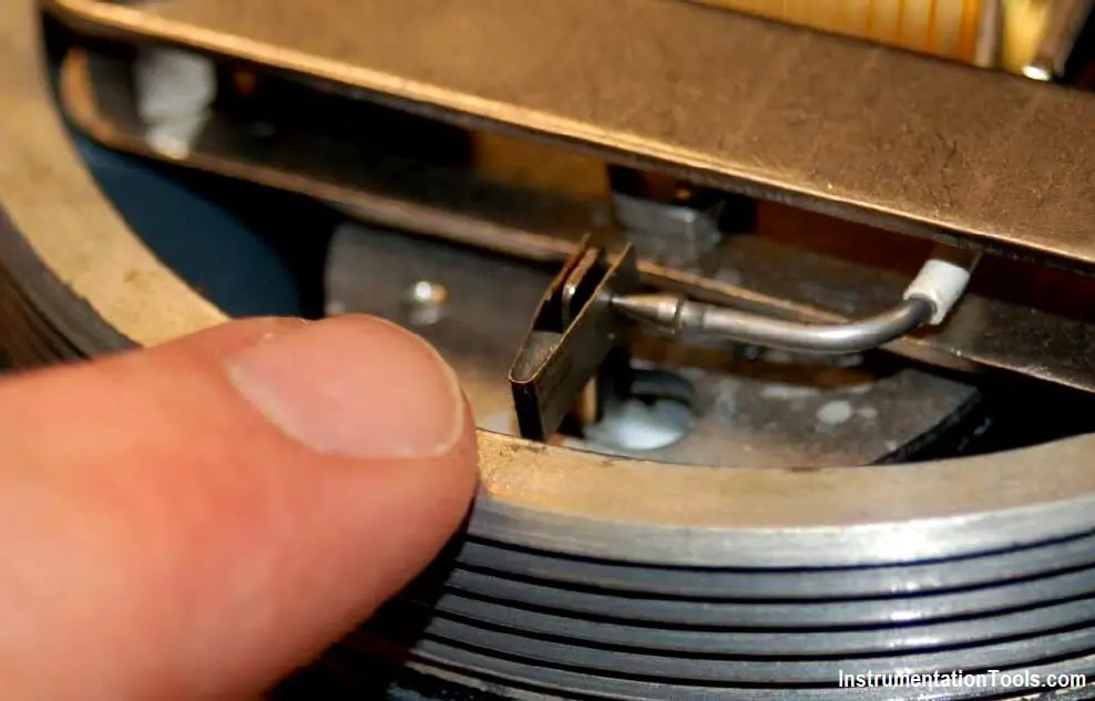
The following photograph shows the range bar and range wheel of the instrument:
As in all instruments, the zero adjustment works by adding or subtracting a quantity, while the span adjustment works by multiplying or dividing a quantity.
In the Foxboro model 13 pneumatic transmitter, the quantity in question is force, since this is a force-balance mechanism.
The zero screw adds or subtracts force to the mechanical system by tensioning a spring, while the range wheel multiplies or divides force in the system by changing the mechanical advantage (force ratio) of a lever.
Foxboro model E69 “I/P” electro-pneumatic transducer
The purpose of any “I/P” transducer is to convert an electrical signal into a corresponding pneumatic signal.
In most cases, this means an input of 4-20 mA DC and an output of 3-15 PSI, but alternative ranges do exist.
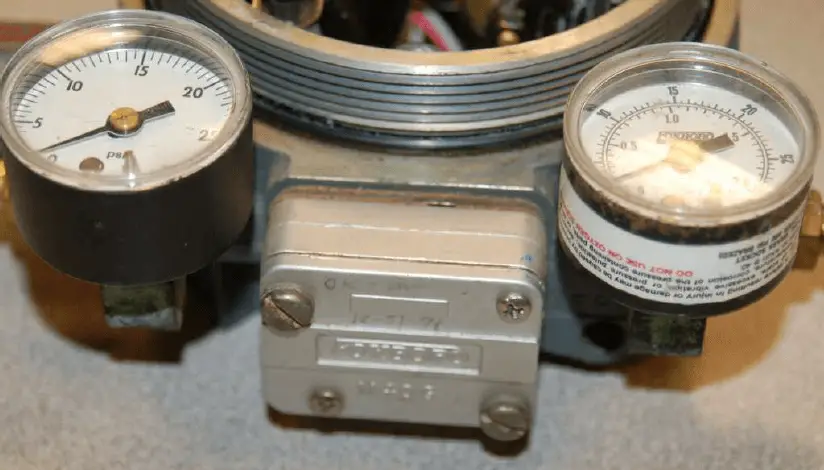
An example of an I/P transducer manufactured by Foxboro is the model E69, shown here:
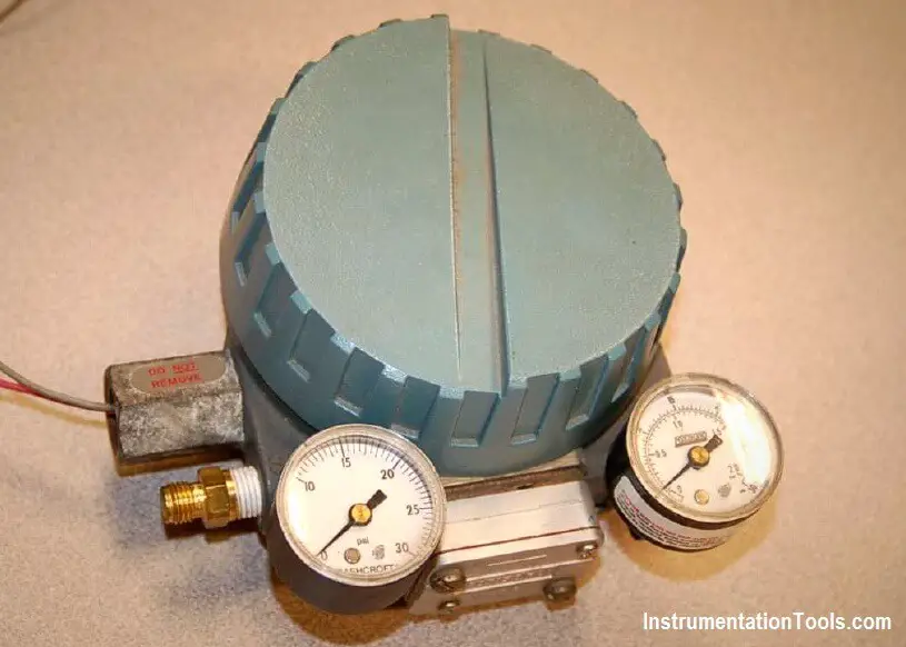
Two pressure gauges indicate supply and output pressure, respectively. Wires convey the 4-20 mA electrical signal into the coil unit inside the transducer.
A view with the cover removed shows the balancing mechanism used to generate a pneumatic pressure signal from the electric current input.
The baffle/nozzle may be seen at the left of the mechanism, the nozzle located at the end of a bent tube, facing the flat baffle on the surface of the circular coil unit:
As electric current passes through the coil, it produces a magnetic field which reacts against a permanent magnet’s field to generate a torque.
This torque causes the coil to rotate counterclockwise (as viewed in the picture), with the baffle connected to the rotating assembly.
Thus, the baffle moves like the needle of an analog electric meter movement in response to current: the more current through the coil, the more the coil assembly moves (and the baffle moves with it).
The nozzle faces this baffle, so when the baffle begins to move toward the nozzle, back-pressure within the nozzle rises. This rising pressure is amplified by the relay, with the output pressure applied to a bellows.
As the bellows expands, it draws the nozzle away from the advancing baffle, achieving balance by matching one motion (the baffle’s) with another motion (the nozzle’s).
In other words, the nozzle “backs away” as the baffle “advances toward:” the motion of one is matched by the motion of the other, making this a motion-balance instrument.
A closer view shows the baffle and nozzle in detail:
Increased current through the wire coil causes the baffle to move toward the right (as pictured) toward the nozzle.
The nozzle in response backs away (also to the right) to hold the baffle/nozzle gap constant. Interestingly, the model E69 transducer employs the same pneumatic amplifying relay used in virtually every Foxboro pneumatic instrument:
This amplifying relay makes the system more responsive than it would be otherwise, increasing sensitivity and precision.
The relay also serves as an air volume amplifier, either sourcing (supplying) or sinking (venting) air to and from a control valve actuator much more rapidly than the nozzle and orifice could do alone.
As in all instruments, the zero adjustment works by adding or subtracting a quantity, while the span adjustment works by multiplying or dividing a quantity.
In the Foxboro model E69 transducer, the quantity in question is motion, since this is a motion-balance mechanism. The zero adjustment adds or subtracts motion by offsetting the position of the nozzle closer to or farther away from the baffle.
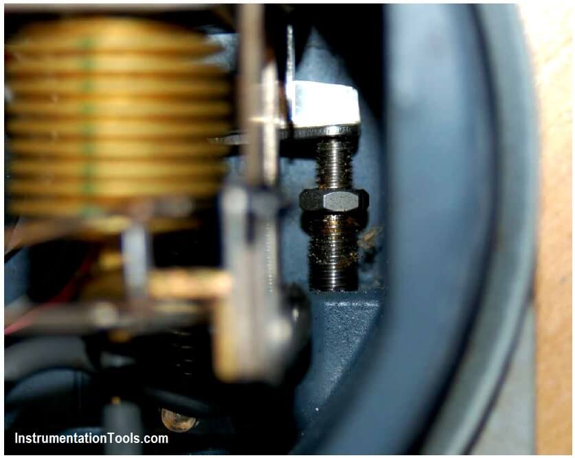
A close-up photograph of the zero adjustment screw shows it pressing against a tab to rotate the mounting base plate upon which the coil unit is fixed.
Rotating this base plate add or subtracts angular displacement to/from the baffle’s motion:
The span adjustment consists of changing the position of the nozzle relative to the baffle’s center of rotation (axis), so that a given amount of rotation equates to a different amount of balancing motion required of the nozzle.
If the nozzle is moved farther away from the baffle’s axis, the same rotation (angle) will result in greater nozzle motion (more output pressure) because the nozzle “sees” greater baffle movement.
If the nozzle is moved closer toward the baffle’s axis, the same rotation (angle) will result in less nozzle motion (less output pressure) because the nozzle “sees” less baffle movement.
The effect is not unlike the difference between a baseball striking the tip of a swung bat versus striking in the middle of a swung bat: the baseball struck by the tip of the bat “sees” a faster-moving bat than the baseball struck by the middle of the bat.
This span adjustment in the E69 mechanism consists of a pair of nuts locking the base of the bellows unit at a fixed distance from the baffle’s axis.
Changing this distance alters the effective radius of the baffle as it swings around its center, therefore altering the gain (or span) of the motion balance system:
Fisher model 546 “I/P” electro-pneumatic transducer
The Fisher model 546 I/P transducer performs the same signal-conversion function (mA into PSI) as the Foxboro model E69, but it does so quite differently.
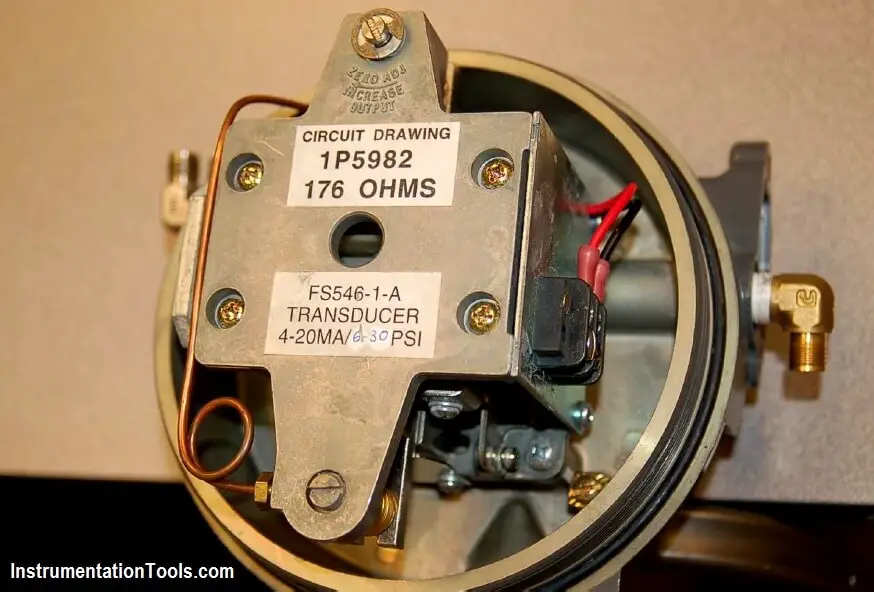
The following photograph shows the internal mechanism of the model 546 transducer with its cover removed:
This particular instrument’s construction tends to obscure its function, so I will use an illustrative diagram to describe its operation:
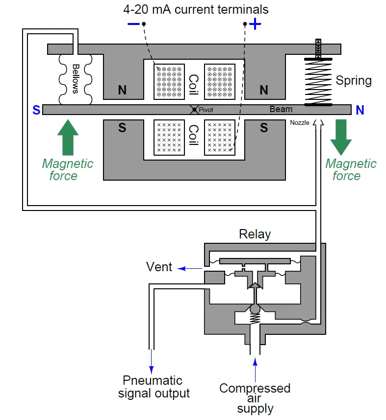
The heart of this mechanism is a ferrous (substance containing the element iron) beam, located between the poles of a permanent magnet assembly, and centered within an electromagnet coil (solenoid).
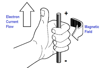
Current passing through the electromagnet coil imparts magnetic poles to the ends of the beam. Following the arrow head/tail convention shown in the coil windings (the dots versus X marks) representing conventional flow vectors pointing out of the page (top) and going into the page (bottom) for the coil wrapped around the beam, the right-hand rule tells us that the beam will magnetize with the right-hand side being “North” and the left-hand side being “South.”
This electro-magnetic polarity interacts with the permanent-magnetic poles to torque the beam clockwise around its pivot point (fulcrum), pushing the right-hand side down toward the nozzle.
Any advance of the beam toward the nozzle will increase nozzle back-pressure, which is then fed to the balancing bellows at the other end of the beam. That bellows provides a restoring force to the beam to return it (nearly) to its original position.
The phenomenon of an input force being counter-acted by a balancing force to ensure negligible motion is the defining characteristic of a force-balance system.
This is the same basic principle applied in the Foxboro model 13 differential pressure transmitter: an input force countered by an output force.
If you examine the diagram carefully, you will notice that this instrument’s amplifying relay is not located within the force-balance feedback loop. The nozzle’s back-pressure is directly fed back to the balancing bellows with no amplification at all.
A relay does exist, but its purpose is to provide a modest (approximately 2:1) pressure gain to raise the nozzle back-pressure to standard levels (3-15 PSI, or 6-30 PSI).
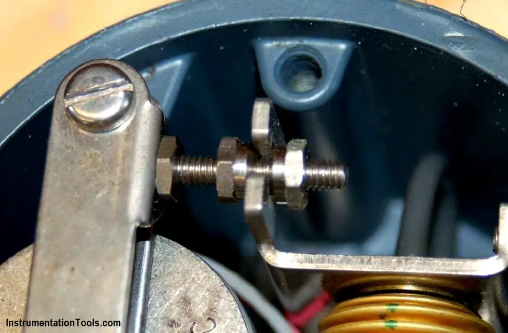
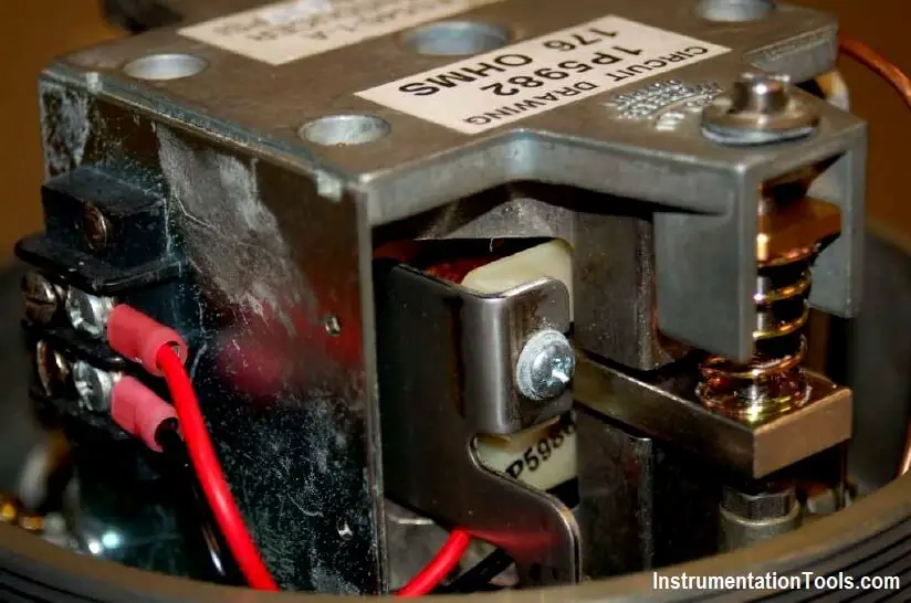
The next photograph shows the solenoid coil, force beam, and nozzle. If you look closely, you can see the copper-colored windings of the coil buried within the mechanism.
The zero-adjustment spring is located above the beam, centered with the nozzle (below the beam):
Fisher manufactured these I/P transducers with two different pneumatic ranges: 3-15 PSI and 6-30 PSI.
The mechanical difference between the two models was the size of feedback bellows used in each. In order to achieve the greater pressure range (6-30 PSI), a smaller feedback bellows was used. This may seem backward at first, but it makes perfect sense if you mentally follow the operation of the force-balance mechanism.
In order to generate a greater air pressure for a given electric current through the coil, we must place the air pressure at a mechanical disadvantage to force it to rise higher than it ordinarily would in achieving balance.
One way to do this is to decrease the effective area of the bellows, so that it takes a greater air pressure to generate the same amount of balancing force on the beam.