Example of a PLC Mixing System Program using Timers and Counters in Omron PLC using Cx-Programmer and Cx-Designer software.
Mixing Program
This PLC article discusses the Batch Mixing System PLC program using CX-Programmer with simulations using CX-Designer. This system will run automatically, the Input Valve will Open when the Tank is empty.
The Mixer Tank uses sensors (HIGH & LOW) to measure the liquid level in the tank. When the tank is full then the input valve will Close. When the tank is full, then the Mixing process will continue at a defined time which has been Set in the HMI (Human Machine Interface) Timer parameter.
When the Mixing process is complete, then the output valve will open and release liquid until the tank is empty. When the Mixing Process has been carried out, it will be recorded using a Counter.
Understanding How PLC Programs Operate?
This PLC program has 3 main buttons, the START (0.00) button is used to turn ON the system, the STOP (0.01) button is used to turn OFF the system, and the RESET_COUNTER (0.04) is used to Reset the Counter value to zero “0”. The memory word SV_TIME (D10) needs to be set before starting the system, the memory word SV_TIME (D10) functions as the “Set Value” of TIMER_MIX (T0000).
When the tank is empty, the NC (Normally Close) contacts of SENS_LOW (0.02) and SENS_HIGH (0.03) sensors will Open the VALVE_IN (100.00). SENS_LOW (0.02) measures the low level of liquid in the tank and SENS_HIGH (0.03) measures the high level of liquid in the tank. When SENS_LOW (0.02) and SENS_HIGH (0.03) change to TRUE state then VALVE_IN (100.00) will be Closed.
The Mixing process will be carried out when VALVE_IN (100.00) is Closed. The mixing process time is determined by the Memory Word SV_TIME (D10) value. The NO (Normally Open) contact of SENS_HIGH (0.03) which has changed to the TRUE condition will Activate TIMER_MIX (T0000) and Output MIXER (100.01). When TIMER_MIX (T0000) has reached its “Set Value” the MIXER Output (100.01) will be Disabled.
When TIMER_MIX (T0000) has reached its “Set Value” it will open the VALVE_OUT (100.02). VALVE_OUT (100.02) will remain in the open state even though the NO (Normally Open) contact of TIMER_MIX (T0000) has been Deactivated because it uses the Interlock function.
VALVE_OUT (100.02) will be Closed when the NO (Normally Open) contact of SENS_LOW (0.02) changes to a LOW state. The value in Memory Word COUNTER (D0) will increase by (+1) when VALVE_OUT (100.02) is Active.
List of I/Os
Addressing Input, Output, TIM, Bit Memory, and Word Memory
| Comment | Input (I) | Output(Q) | Memory Word | Memory Bits | Timer |
| START | 0.00 | ||||
| STOP | 0.01 | ||||
| SENS_LOW | 0.02 | ||||
| SENS_HIGH | 0.03 | ||||
| RESET_COUNTER | 0.04 | ||||
| VALVE_IN | 100.00 | ||||
| MIXER | 100.01 | ||||
| VALVE_OUT | 100.02 | ||||
| SYSTEM_ON | W0.00 | ||||
| TIMER_MIX | T0000 | ||||
| COUNTER | D0 | ||||
| SV_TIME | D10 |
PLC Program
RUNG 0
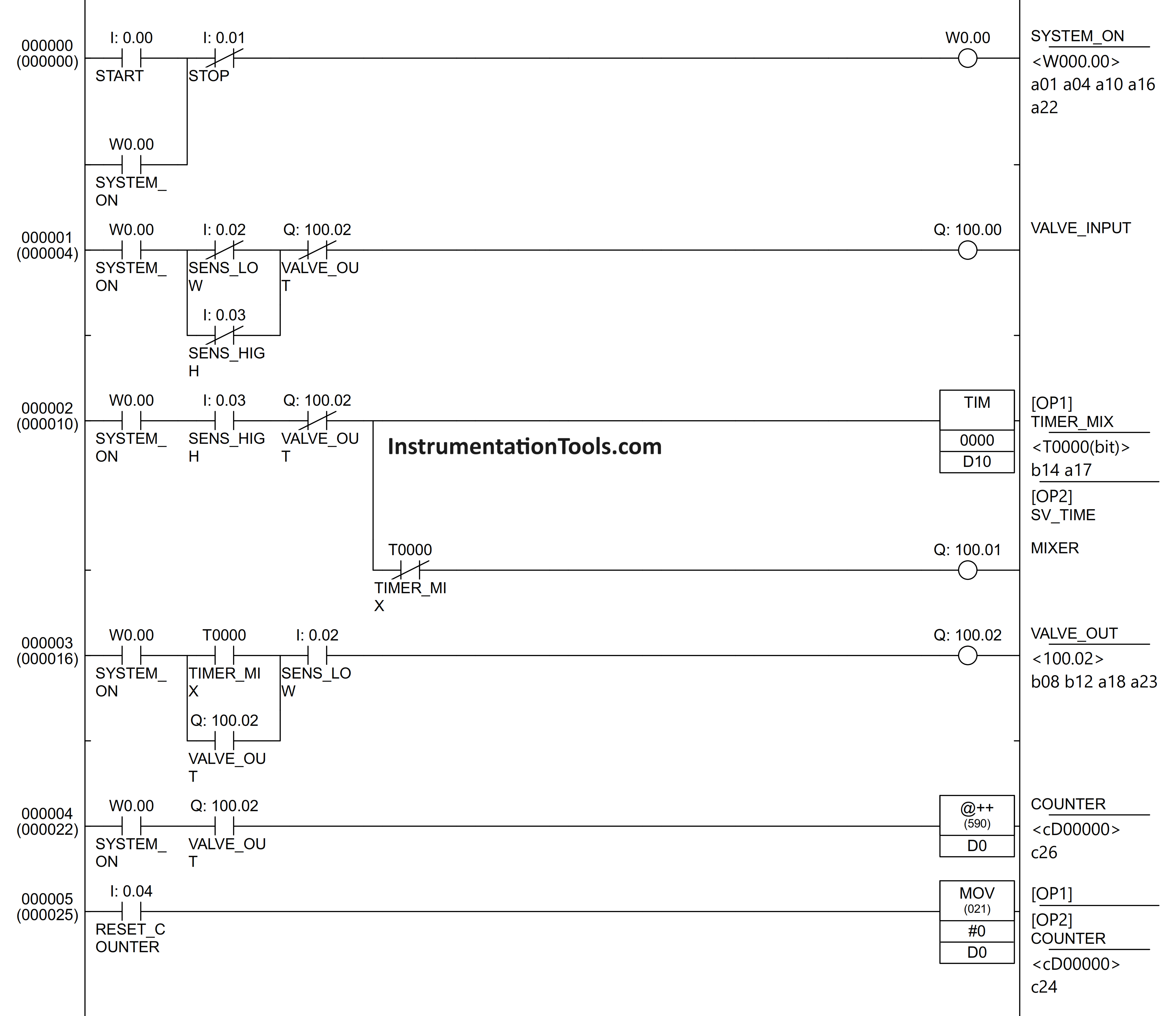
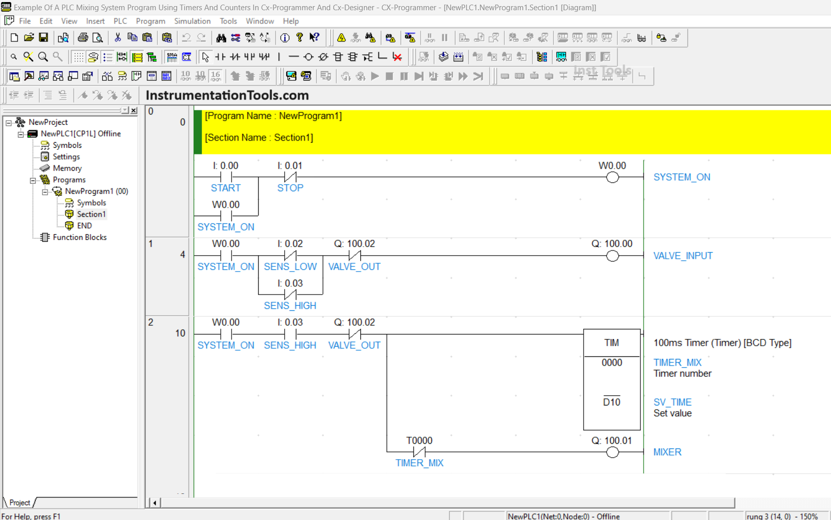
When the START (0.00) button is pressed then the SYSTEM_ON (W0.00) Bit Memory will be Active. Because it uses the latching function, the SYSTEM_ON (W0.00) Bit Memory will remain active even though the START (0.00) button is released. Memory Bit SYSTEM_ON (W0.00) will be Disabled if the STOP (0.01) button is pressed.
RUNG 1
The VALVE_INPUT (100.00) output will be Open when the NO (Normally Open) SYSTEM_ON (W0.00) contact will be ON and it will be OFF when the NC (Normally Close) contacts of SENS_LOW (0.02), SENS_HIGH (0.03), and VALVE_OUT (100.02) are Active.
RUNG 2
When the NO (Normally Open) contacts of SYSTEM_ON (W0.00) and SENS_HIGH (0.03) are Active, TIMER_MIX (T0000) will Start counting and the MIXER (100.01) output will be Active. When TIMER_MIX (T0000) has reached its “Set Value”, the MIXER (100.01) Output will be Disabled.
RUNG 3
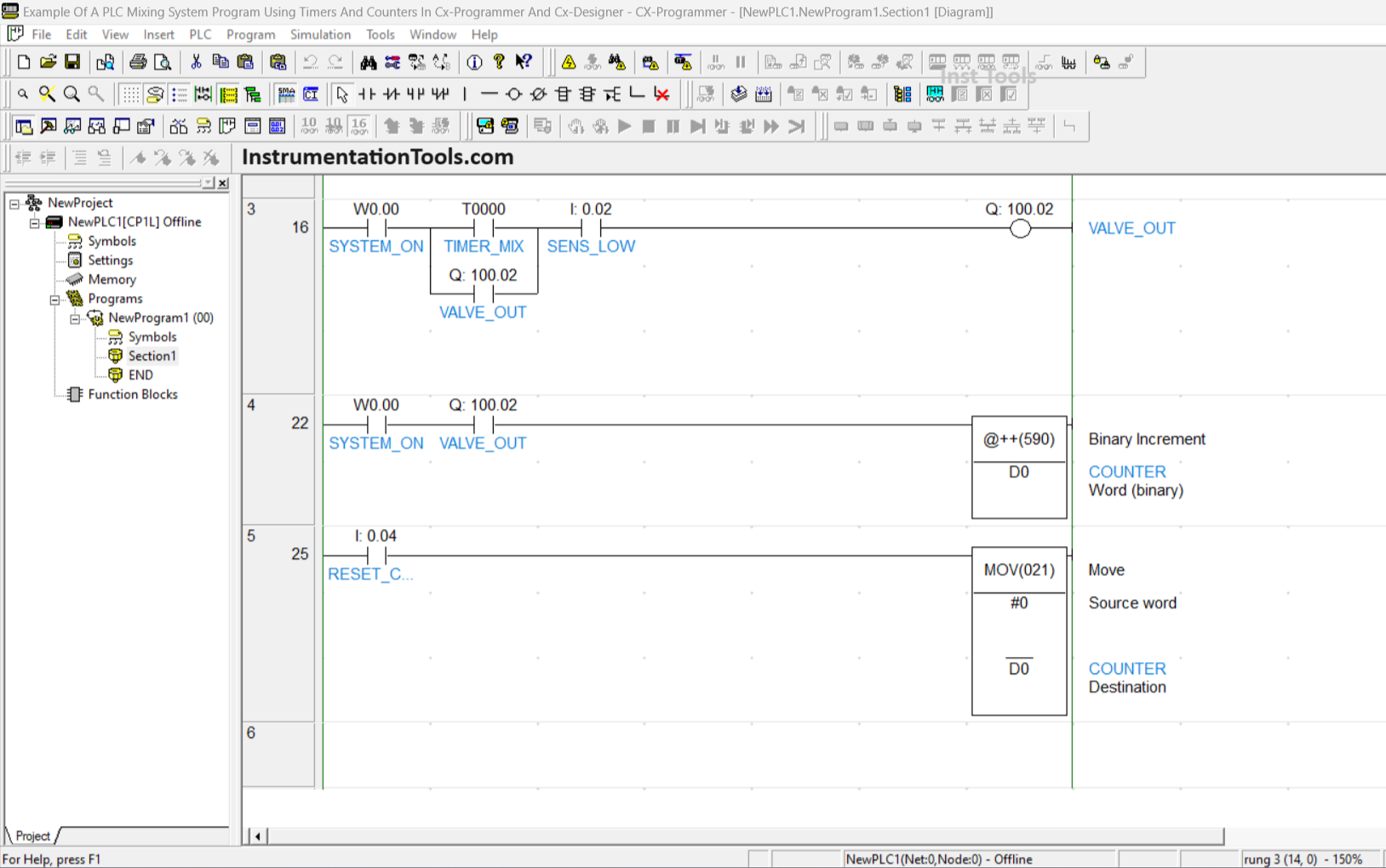
When the NO (Normally Open) TIMER_MIX (T0000) contact has reached its “Set Value” and the SENS_LOW (0.02) contact is Active, the VALVE_OUT (100.02) Output will be Active. The VALVE_OUT (100.02) output will remain active even though the NO (Normally Open) TIMER_MIX (T0000) contact has been disabled due to the Interlock Function.
The VALVE_OUT (100.02) output will be Disabled when the NO (Normally Open) SENS_LOW (0.02) and SYSTEM_ON (W0.00) contacts are Disabled.
RUNG 4
COUNTER (D0) will increase by (+1) when the NO (Normally Open) contacts of VALVE_OUT (100.02) and SYSTEM_ON (W0.00) are Active.
RUNG 5
The MOV instruction will move the zero value “0” to the Memory Word COUNTER (D0) when the RESET_COUNTER (0.04) contact is Activated.
Program Simulation
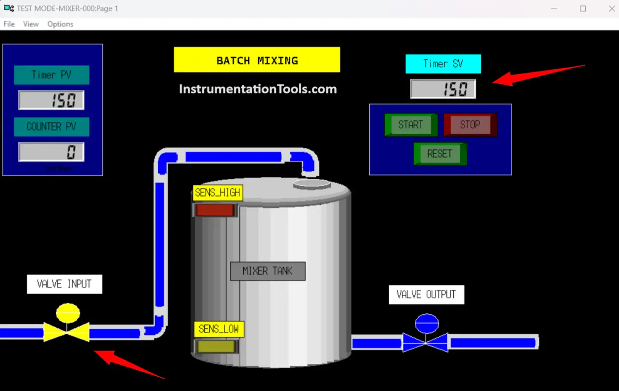
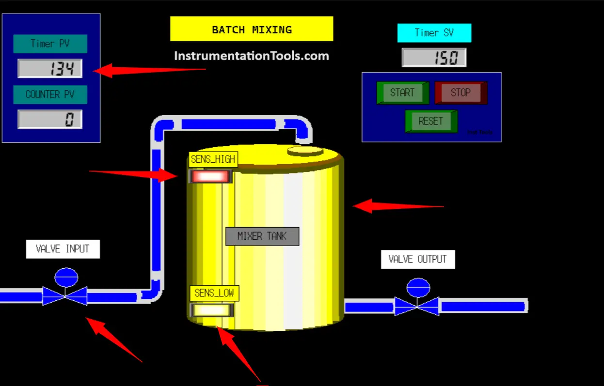
The image above shows the conditions when the system has been Started and the Timer “Set Value” has been Set to “150”. You can see VALVE_INPUT (100.00) is Active.
The image above shows the conditions when the Mixing process is being carried out.
You can see that the MIXER (100.01), SENS_LOW (0.02), and SENS_HIGH (0.03) outputs are Active. The image also shows the value of the PV Timer Starting to count down.
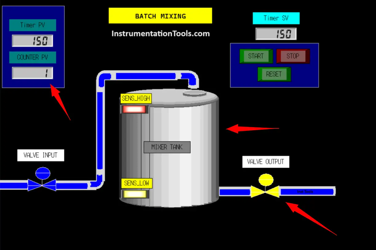
The image above shows the conditions when the Mixing process has finished and VALVE_OUT (100.02) is Active. It can be seen that the value on COUNTER PV has the value “1”.
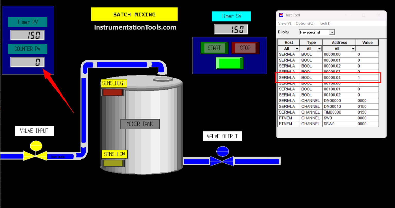
The image above shows the conditions when the RESET_COUNTER button (0.04) is activated. You can see the value on the PV COUNTER has changed to zero “0”.
Download PLC Program: Click Here
If you liked this article, please subscribe to our YouTube Channel for PLC and SCADA video tutorials.
You can also follow us on Facebook and Twitter to receive daily updates.
Read Next:
- Parking Garage Indicator PLC Automation
- Pump and Mixer Operations PLC Timer Control
- Glass Cutting and Polishing Machine Automation
- Exhaust Fan Control Example PLC Programming
- Motion Detection based Street Light PLC Logic


THE CX DESGINER HAS BEEN DELETED. CAN I HOW CAN I TEST IT??
THE CX DESGINER HAS BEEN DELETED.
CAN I HOW CAN I TEST IT??