Magnetic level gauge work on the principle of communicating vessels, therefore the level in the measuring chamber will be the same as the level in the vessel. The measuring chamber is fitted with a float, which has a magnet inside.
The float with magnet will float on the medium and the magnet in the float will turn the flaps of the indicating rail. The float in the measuring tube is standard not pressurized and has no magnetic or mechanical guidance.
This construction makes the float less dangerous than a float which is standard pressurized. When necessary Hadro can produce a pressurized float.

Each flap in the indicating rail is fitted with a permanent magnet which makes this level gauge unaffected by shocks, vibrations and high temperatures. Also moisture and / or an aggressive environment are no problem for this level gauge.
This magnetic level gauge is available with plastic or stainless steel flaps. The flaps can be placed in a plastic, aluminium or stainless steel housing.
Because of the construction of the flaps, one side white and on the other red / orange it is possible to see the level over a greater distance or in darker places.
With the available “Pointers” it is possible to set the visual limits on the indicating rail on every level you require.
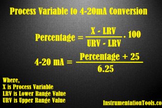
When the magnetic level gauge is fitted with magnetic switches it is possible to get a signal. With more switches you can make a pump control (pump on / off) and / or create a high / low alarm. Beside or instead of level switches a reedchain transmitter can be mounted, this reedchain has an standard output signal of 4-20 mA.
Magnetic level gauge are also suitable for interface reading. The float will sink into the medium with the lower density and will float on the medium with the higher density.
Magnetic Level gauge Floats
All the magnetic level gauges are fitted with a float. This float is standard in stainless steel, but the float is also available in Titanium or Hastelloy. The float must have enough buoyancy and the magnet must be fitted at the right position inside the float. So it is always important to select a float which is suitable for the process conditions.
With the below mentioned process conditions it is possible to select a float which will float on the medium.
- Medium
- Density
- Working pressure
- Operating Temperature
The lowest density, for which vendor can supply a float is 380 kg/m3 but this is depending on the before mentioned process conditions. When a fluid is very aggressive we can also coat the float with a suitable lining.
When we have a choice between an open float or a pressurised float we prefer the pressurized float. Because the open float will eventually sink, condensate will build up inside the open float. For example our pressurized floats are suitable for 208 bar at 375°C with a density of 650 kg/m3 .
The float inside a magnetic level gauge can be fitted with a torriodal (360°) magnet or a magnetic bar. All our floats are fitted standard with a torriodal-magnet, because a float with a magnetic bar can loose there guidance/ indication rail by rapid movement inside the level gauge.
As a result the magnetic level gauge will not work properly for a while. Torriodal magnets are not affected by rapid movements of the float and can move freely inside the level gauge. This is also why you can place a level switch at all the sides you want.
Switches
When you mount a magnetic switch on the level gauge it is possible to get a signal. With more switches you can make a pump control (pump on / off) and / or obtain a high / low alarm.
Reedchain for an analog output signal
By using a reedchain it is possible to become a 4-20 mA signal. The reedchain is standard mounted on the complete length of the magnetic level gauge.
Reference – Precision Fluid Controls
Articles You May Like :
Magnetic Level Gauge Animation


A magnetic level gauge is a type of level sensor, i.e., a define used to measure the level of fluids. A magnetic level gauge includes a “floatable” device that can float both in high and low density fluids. Magnetic level gauges may also be designed to accommodate severe environmental conditions up to 210 bars at 370 °C.
Magnetic float level sensors involve the use of a permanent magnet sealed inside a float whose rise and fall causes the opening or closing of a mechanical switch, either through direct contact or in proximity of a reed switch. With mechanically actuated floats, the float is directly connected to a micro switch.
For both magnetic and mechanical float level sensors, chemical compatibility, temperature, specific gravity (density), buoyancy, and viscosity affect the selection of the stem and the float. For example, larger floats may be used with liquids with specific gravities as low as 0.5 while still maintaining buoyancy.
The choice of float material is also influenced by temperature-induced changes in specific gravity and viscosity – changes that directly affect buoyancy.
Exploring the physics and engineering behind this design, requires looking at basic magnetism. A standard bar magnet has two magnetic poles: north and south. (The north will read positive on a gauss meter and the south will read negative.) Magnetic field are mapped using magnetic flux lines.
These lines are a graphical representation of the magnetic field density. They show the direction of flow for the magnetic field and represent relative field strength – the closer together the lines are, the stronger the magnetic field. Flux lines will always travel from the north pole to the nearest south pole and always leave and enter surfaces at 90°, or perpendicular to the surface.
They can only travel in straight lines or curved paths, which means they can never make a sudden, abrupt change in direction. Flux lines will also always follow a path of least magnetic resistance. Most importantly, they can never cross one another.
When selecting a magnetic level gauge it is important to take into account the strength of the magnetic field. The magnetic field is the heart of the magnetic level gauge – the stronger the field, the more reliable the instrument will function.
Some manufacturers rely on a single magnet for their magnetic level gauges which causes the strength of the north field to be identical to, and as weak as, the south field.
It is apparent that at the location of the indicators, switches and transmitters, the field would not be as intense. Some manufacturers use a single annular ring magnet, others use a series of single bar magnets in a circular array in their float design.
In this design the relative field strength of the north and south poles will be equal to one another and less than that of a dual magnet design. Moreover, the field strength as you travel around the circumference will have high and low spots as you pass between the individual bar magnets.