Interface level calculation is not complicated.
If we just have our basics concepts clear it is very straight forward.
First simple pressure measurement formula

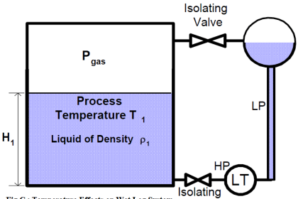
The pic above shows a Container of Height 100 Inches
And this tank contains Liquid of Specific gravity 0.9
So what is the pressure at the bottom?
Height x Specific gravity = InH2O
100 (inches) X 0.9 = 90 inH2O
This Formula is adapted from Rosemount technical Datasheet (paper no :- 00816-0100-3207)
Note :- Specific gravity :- It compares with Density of substance with that of WATER (H2O)
Hence when we multiply ,
Height (Inches) x S.G ( Comparing with Density of substance with that of WATER (H2O))
= inH2O (The unit we get as product)
This our Simple Formula that we will be using.
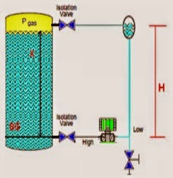
Interface Level Calculation
One prerequisite recommended for this system is to fill impulse lines with Heavier fill fluid.
At 4mA Case ( Zero interface level ) :-

In this case the entire portion we are measuring will be filled with “Lighter fluid” .
So as per our formula
Pressure at HP tapping = Height X Specific gravity
Pressure at HP tapping = 100 inches X 0.5 = 50 inH2O
(One prerequisite recommended for this system is to fill LP impulse lines with Heavier fill fluid to get stable reading at 20mA )
Hence
Pressure at LP tapping = Height X Specific gravity
Pressure at LP tapping = 100 inches X 1 = 100 inH2O
Differential pressure of Transmitter = H.P – L.P
Differential pressure of Transmitter = 50 inH2O – 100 inH2O = -50 inH2O
It means at -50 inH2O transmitter will give 4mA
Hurry we are already half way !!!!!
At 20mA Case ( When tank is full with Heavy fluid)

As per our formula
Pressure at HP tapping = Height X Specific gravity
Pressure at HP tapping = 100 inches X 1 =100 inH2O
Pressure at LP tapping = Height X Specific gravity
Pressure at LP tapping = 100 inches X 1 =100 inH2O (as LP tapping is filled with Heavier fluid)
Differential pressure of Transmitter = H.P – L.P
Differential pressure of Transmitter = 100 inH2O – 100 inH2O = 0 inH2O
It means at 0 inH2O transmitter will give 20mA
So here’s our calibration range “-50 inH2O to 0 inH2O”
For Extra information, what if we need to know what would transmitter give at 50% of Interface
Case 3 ( 50% is filled with Lighter fluid and 50% is filled with heavier fluid)

50 % of transmitter output will be 12mA transmitter at-25inH2O (Half of total calibration range -50inH2O to 0inH2O )
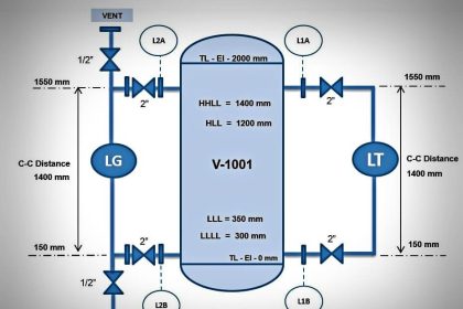
Interface = { (D.P by transmitter – Lower calibration range)/Span } X Total C-C distance
Here C-C distance nothing but center to center of measuring distance, as shown in above picture.
I = { ( -25 inH2O – (-50 inH2O) ) X 50inH2O } X 100 inH2O
Interface = 50 inH2O
Cross checking
Our total distance is 100 inches of H2O
When interface is at 50% means Interface between Lighter and heavier fluid will be at 50 inH2O
Thanks for reading !
Author : Asad Shaikh
Profile : Linkedin
Articles You May Like
Thermowell Installation Problem