Inst ToolsInst ToolsInst Tools
  • Courses
  • Automation
    • PLC
    • Control System
    • Safety System
    • Communication
    • Fire & Gas System
  • Instrumentation
    • Design
    • Pressure
    • Temperature
    • Flow
    • Level
    • Vibration
    • Analyzer
    • Control Valve
    • Switch
    • Calibration
    • Erection & Commissioning
  • Interview
    • Instrumentation
    • Electrical
    • Electronics
    • Practical
  • Q&A
    • Instrumentation
    • Control System
    • Electrical
    • Electronics
    • Analog Electronics
    • Digital Electronics
    • Power Electronics
    • Microprocessor
  • Request
Search
  • Books
  • Software
  • Projects
  • Process
  • Tools
  • Basics
  • Formula
  • Power Plant
  • Root Cause Analysis
  • Electrical Basics
  • Animation
  • Standards
  • 4-20 mA Course
  • Siemens PLC Course
Reading: Magnetic Flow Meter Liner Damaged and Winding Burnt
Share
Font ResizerAa
Inst ToolsInst Tools
Font ResizerAa
  • Courses
  • Design
  • PLC
  • Interview
  • Control System
Search
  • Courses
  • Automation
    • PLC
    • Control System
    • Safety System
    • Communication
    • Fire & Gas System
  • Instrumentation
    • Design
    • Pressure
    • Temperature
    • Flow
    • Level
    • Vibration
    • Analyzer
    • Control Valve
    • Switch
    • Calibration
    • Erection & Commissioning
  • Interview
    • Instrumentation
    • Electrical
    • Electronics
    • Practical
  • Q&A
    • Instrumentation
    • Control System
    • Electrical
    • Electronics
    • Analog Electronics
    • Digital Electronics
    • Power Electronics
    • Microprocessor
  • Request
Follow US
All rights reserved. Reproduction in whole or in part without written permission is prohibited.
Inst Tools > Blog > Root Cause Analysis (RCA) > Magnetic Flow Meter Liner Damaged and Winding Burnt

Magnetic Flow Meter Liner Damaged and Winding Burnt

Instrumentation engineering root cause analysis of magnetic flow meter liner damaged and winding burnt problem.

Last updated: September 28, 2022 2:51 pm
S Raghava Chari
Root Cause Analysis (RCA)
1 Comment
Share
6 Min Read
SHARE

Instrumentation engineering root cause analysis of magnetic flow meter liner damaged and winding burnt.

Contents
Magnetic Flow Meter Liner DamagedMagmeter Recovery Benefits
Article Type:Root Cause Analysis (RCA)
Category:Instrumentation
Equipment Type:Instruments
Author:S. Raghava Chari

Note: This root cause analysis (RCA) is from real-time scenarios that happened in industries during the tenure of two or three decades ago. These articles will help you to improve your troubleshooting skills and knowledge.

Magnetic Flow Meter Liner Damaged

None could repair winding burnt & Extensively Damaged flow tube liner Magnetic Flow Meter.

Problem: The mag flow meter flow tube (FT) is 800 mm long 1”Sch 40 both ends collared and CS loose-flanged SS pipe spool. 3 mm thick PTFE or similar electricity insulating process compatible lining insulates the flowing liquid from the SS pipe along the FT length.

The manufacturer declined relining the FT and even supplying a replacement lined tube telling no field repair possible. Relining vendors also declined telling the too small bore pipe lining is impractical.

The author lined it himself thus and put the mag meter back online:

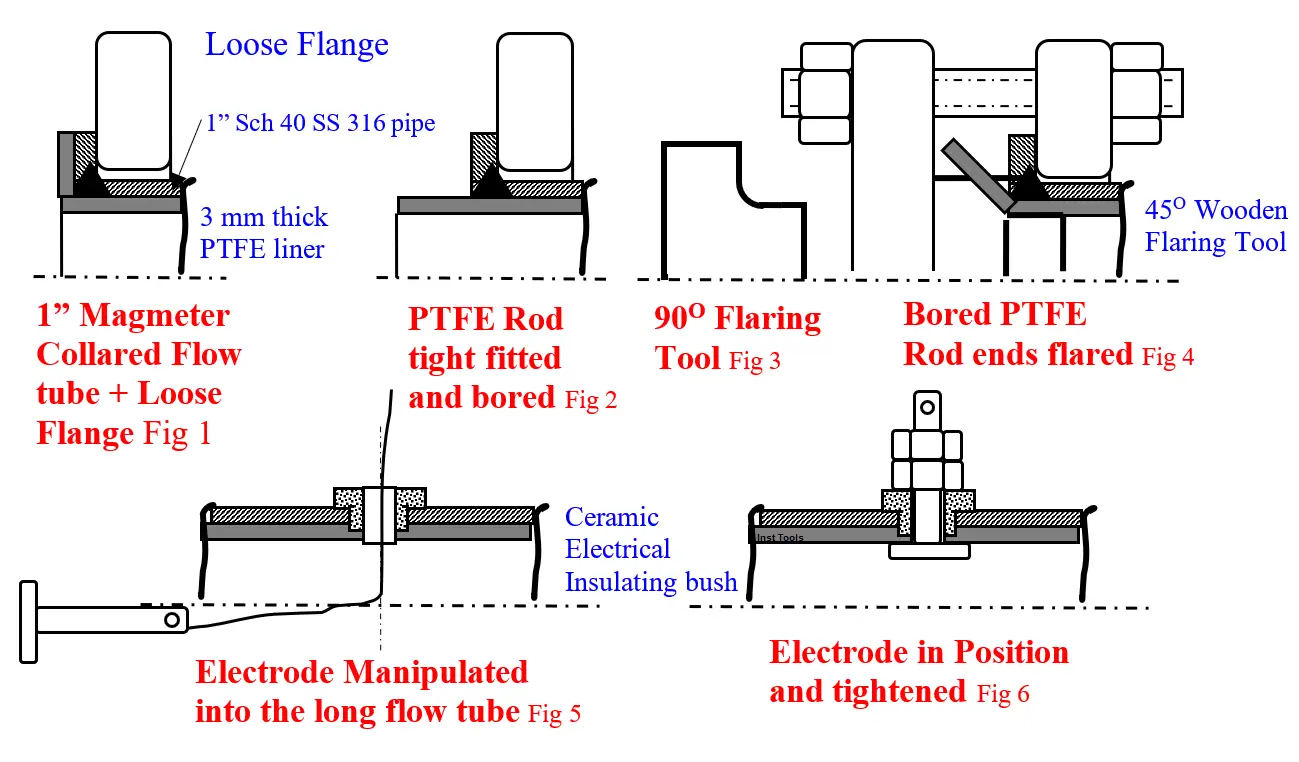
  1. Unscrew and save the electrodes and their ceramic bushes, scrape out damaged the liner to bare the metal and sand blast tube bore
  2. Cut a bought out 30-mm dia carbon filled Teflon rod – rod from now on – to length = collar-to-collar FT length L+100 mm
  3. Reduce the rod dia for hand pushing into FT uniformly flame heated to ≈ 200o C
  4. Light-tight vice hold the FT and Insert the rod into the FT both ends projecting equally. Allow to cool to room temperature
  5. Bore the rod 20 mm ID.
  6. Flare the ends using shop made 45o, and 90o 6 mm radius fillet radius flaring tools – see fig. Cut out the excess liner protruding beyond collar OD
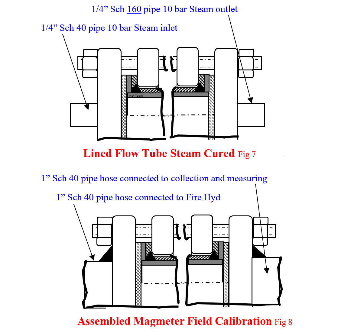
  7. Make 10 mm thick x 1” 150 # flange raised face dia CS plate 1; Screw in a ¼” Sch 40 NPT threaded short nipple at the center. Likewise make 1/8” NPT screwed CS plate 2.
  8. Bolt plate 1 to FT left side using CS flange and plate 2 to FT right with proper gaskets
  9. Connect 10 bar steam to plate 1 and leave plate 2 free Maintain 4-hours steam flow to cure the liner to the SS pipe 
  10. Remove the curing steam connections
  11. Drill hole in the liner at the FT electrode hole location and insert the saved ceramic bush
  12. Pass a long noose ended twine via the ceramic bush, and pull it out FT left end. Untie the noose, insert it via the electrode hole and tie the electrode. Pull the ceramic bush end string, manipulate the electrode via the ceramic bush with a wooden scale or similar flat wood piece and tighten the electrode nut. Remove the twine. Now top electrode is in position
  13. Insert and tighten bottom electrode to FT the same way
  14. Assemble the coils over the lined FT. Mag Meter is ready for use.
  15. E.g. we want to calibrate the head for 0-300 LPM i.e. 0 to 15.92 m/sec liquid velocity for this head of 20 mm bore. Hence, connect the placed on floor head to a table held receiver instrument of scale 0-300 LPM calibrated for 15.92 m/s velocity
  16. Connect a fire hose to FT left flange (see fig). Hose connect FT right flange to a reference meter e.g. target flow transmitter. Alternatively arrange to collect and weigh water flown during stopwatch-timed period.
  17. At zero flow and making sure of water filled FT, the reason for placing the magmeter on floor and bolting me magmeter to upwards flow pipelines – adjust left potentiometer on the head to make the mag meter receiver read zero. Open the fire hydrant and adjust the flow for say 250 LPM shown by the reference. Adjust the head span potentiometer. Verify the reading near midscale.
  18. Dissemble the set up; return the various components. The mag meter is for plant use.
Magnetic Flow Meter Liner Damaged
Assembled Magmeter Field Calibration

Magmeter Recovery Benefits

See the benefits below.

  • Enabled production reduction within 8-hours and met the committed orders
  • Besides the financial gains, it preserved image as a reliable phosphate fertilizer supplier
  • Saved a head purchase costs
  • Found a way to handle future such problems

Author: S. Raghava Chari

Do you face any similar issues? Share with us through the below comments section.

If you liked this article, then please subscribe to our YouTube Channel for Instrumentation, Electrical, PLC, and SCADA video tutorials.

You can also follow us on Facebook and Twitter to receive daily updates.

Read Next:

  • Pressure Switch Screwed Cover
  • Doubtful Temperature Readings
  • Pressure Switch Screwed Cover
  • Level Instruments Stopped Working
  • Thermowell Shank to Flange Leaks
Don't Miss Our Updates
Be the first to get exclusive content straight to your email.
We promise not to spam you. You can unsubscribe at any time.
Invalid email address
You've successfully subscribed !

Continue Reading

Premature Arc Fault Breaker Failures
Unreliable Ammonia Flow Transmitter Reading and Problems
Root Cause Analysis for Plant Trip Due to Work on Incorrect Tag
Critical High KiloWatt Motor Winding Burnout Threats
Rotary Drier Shell to Split Gear drive eliminates too frequent drive failures
Steam Turbine Driven Centrifugal Compressors Leak due to Broken Instrument
Share This Article
Facebook Whatsapp Whatsapp LinkedIn Copy Link
Share
1 Comment
  • Sourabh K says:
    September 29, 2021 at 10:44 am

    Very informative info of mag meters

    Reply

Leave a Reply Cancel reply

Your email address will not be published. Required fields are marked *

Stay Connected

128.3kFollowersLike
69.1kFollowersFollow
210kSubscribersSubscribe
38kFollowersFollow

Categories

Explore More

8000 RPM 8000 kW Turbine Problem
Compressor Anti-Surge Control near-miss incident
A Plant Bucket Elevators chains too short chain lives problem eliminated
Steam Letdown Station Problems and their Solutions
Panel and Field Pneumatic Controller’ Bumpless Transfer Issues
Ammonia Flash Vessel All Level Instruments Stopped Working
Erratic Stroking Control Valves Delaying the Shutdown Plant Restart
Cooling Tower Fans Frequently Failing

Keep Learning

Thermocouples Problem

Fire burnt Ammonia Converter Thermocouples Problem

Rotary Granulator Drive

Rotary Granulator Drive Root Cause Analysis (RCA)

Malfunctioning Inlet Check Valves

Malfunctioning Inlet Check Valves caused chaos at Compressor stop/trip

Replace Failed Motors Quickly and Easily

Replace Failed Motors Quickly and Easily

Gearbox within week Failing Journal Bearing upset Plant Operations

Gearbox within week Failing Journal Bearing upset Plant Operations

Fan Motor Frequent Journal Bearing Failures

Fan Motor Frequent Journal Bearing Failures Posed Plant Outages

Repeat Safety Valve Popping

Repeat Safety Valve Popping caused Urea Plant Shutdown

old Pressure Switches

Pressure Switch Frozen Screwed Cover Extends the Plant Shutdown

Learn More

GuideLines for Loop Checks

How to Do Loop Checks During Plant Pre-Commissioning

Standard Colors in PLC Automation Systems

Standard Colors in PLC Automation Systems

Multiphase Flow Meter Calibration Procedure

Multiphase Flow Meter Calibration Procedure

Temperature Transmitter Foundation Fieldbus Configuration

Foundation Fieldbus Temperature Transmitter Configuration

Motor Rotating Magnetic Field

AC Motor Theory

VLSI Projects for Engineering Students

700+ VLSI Projects for Engineering Students

Time Response Analysis

Time Response of Second Order Systems – IV

Configuration of Siemens Scada and PLC

#12 PLC Best Practices – Validate Inputs based on Physical Plausibility

Menu

  • About
  • Privacy Policy
  • Copyright

Quick Links

  • Learn PLC
  • Helping Hand
  • Part Time Job

YouTube Subscribe

Follow US
All rights reserved. Reproduction in whole or in part without written permission is prohibited.
Welcome Back!

Sign in to your account

Username or Email Address
Password

Lost your password?