Inst ToolsInst ToolsInst Tools
  • Ask
  • Courses
  • Videos
  • Q & A
    • Interview
      • Instrumentation
      • Electronics
      • Electrical
      • Practical Questions
    • MCQ
      • Instrumentation MCQ
      • Electrical MCQ
      • Electronics MCQ
      • Control Systems MCQ
      • Analog Electronics MCQ
      • Digital Electronics MCQ
      • Power Electronics MCQ
      • Microprocessor MCQ
      • Multiple Choice Questions
  • EE
    • Electronics
      • Electronics Q & A
      • Electronic Basics
      • Electronic Devices & Circuits
      • Electronics Animation
      • Digital Electronics
    • Electrical
      • Electrical Basics
      • Electrical Q & A
      • Power Electronics
      • Electrical Machines
      • Electrical Animation
      • Power Systems
      • Switchgear & Protection
      • Transmission & Distribution
  • Measure
    • Control Valves
    • Calibration
    • Temperature
    • Pressure
    • Flow
    • Level
    • Analyzers
    • Switches
    • Vibration
    • Solenoid Valve
  • Control
    • PLC Tutorials
    • Control Systems
    • Safety Instrumented System (SIS)
    • Communication
    • Fire & Gas System
  • More
    • Design
    • Tools
    • Animation
    • Basics
    • Formulas
    • Standards
    • TextBooks
    • Common
    • Software
    • Excel Tools
    • Erection & Commissioning
    • Process Fundamentals
    • Videos
    • Books
Search
All rights reserved. Reproduction in whole or in part without written permission is prohibited.
Reading: Magnetic Float Level Transmitter Working Principle
Share
Notification Show More
Font ResizerAa
Inst ToolsInst Tools
Font ResizerAa
  • Courses
  • PLC Tutorials
  • Control Systems
Search
  • Ask
  • Courses
  • Videos
  • Q & A
    • Interview
    • MCQ
  • EE
    • Electronics
    • Electrical
  • Measure
    • Control Valves
    • Calibration
    • Temperature
    • Pressure
    • Flow
    • Level
    • Analyzers
    • Switches
    • Vibration
    • Solenoid Valve
  • Control
    • PLC Tutorials
    • Control Systems
    • Safety Instrumented System (SIS)
    • Communication
    • Fire & Gas System
  • More
    • Design
    • Tools
    • Animation
    • Basics
    • Formulas
    • Standards
    • TextBooks
    • Common
    • Software
    • Excel Tools
    • Erection & Commissioning
    • Process Fundamentals
    • Videos
    • Books
Follow US
All rights reserved. Reproduction in whole or in part without written permission is prohibited.
Inst Tools > Blog > Level Measurement > Magnetic Float Level Transmitter Working Principle

Magnetic Float Level Transmitter Working Principle

Last updated: October 30, 2019 12:43 pm
Editorial Staff
Level Measurement
No Comments
Share
1 Min Read
SHARE

The magnetic float level transmitter devices using the principles of buoyancy and magnetism to generate a changing electrical output in response to the rise and fall of the float on the sensing guide rod.

Contents
Magnetic Float Level TransmitterMagnetic Float Level Transmitter Construction

Magnetic Float Level Transmitter

Magnetic Float Level Transmitter Circuit

The magnetic float level transmitter provides a 3-wire resistance output or can be equipped with an appropriate level transmitter to provide a 4-20mA analog signal indicating liquid level.

The sensing guide rod includes a series of reed switches along the entire measuring length. Placement of reed switches provides either of two possible measuring resolutions.

Magnetic Float Level Transmitter Working Principle

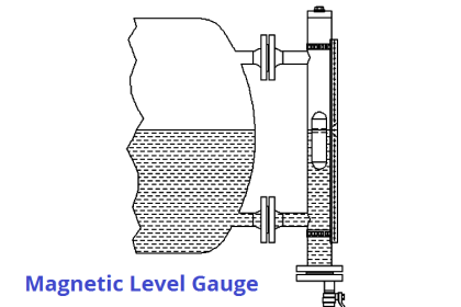
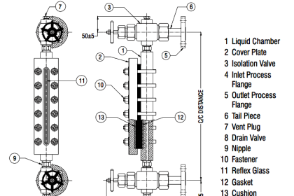
The “Magnet Float Level Transmitter” is composed of a float and sensing rod (shown below).

As the float is raised or lowered by the liquid level, the sensing rod will induce a resistance output, which is directly proportional to the liquid level.

The Magnet Float Level Transmitter is a sturdy, reliable and durable device that is applicable across most industries.

Magnetic Float Level Transmitter Construction

Magnetic Float Level Sensor Principle

Source : FineTek

Don't Miss Our Updates
Be the first to get exclusive content straight to your email.
We promise not to spam you. You can unsubscribe at any time.
Invalid email address
You've successfully subscribed !
Tilt Level Switch Working Animation
Zero Suppression and Zero Elevation Calculations
Siemens Differential Pressure Transmitter Calculations (Flange Type)
Calibration of Displacer Level Transmitter
Open Tank Level Measurement using DP Transmitter
Share This Article
Facebook Whatsapp Whatsapp LinkedIn Copy Link
Share
Leave a Comment

Leave a Reply Cancel reply

Your email address will not be published. Required fields are marked *

Stay Connected

128.3kFollowersLike
69.1kFollowersFollow
208kSubscribersSubscribe
38kFollowersFollow

Categories

Recent Comments

  • Guifty Shimica on Top Non-PLC Certification Courses for Automation Professionals
  • Guifty Shimica on Top Non-PLC Certification Courses for Automation Professionals
  • MIHARITSOA Aina Sitraka on Top Non-PLC Certification Courses for Automation Professionals
  • Vaishnavi on Free Instrumentation Course for Trainee Engineers

Related Articles

Capillary Remote Seal Leave Measurement

Siemens Pressure Transmitter with Remote Seals Calculations

Closed-tank-DP-Level-Transmitter-with-wet-leg-elevation-zero-direct-mount-Calibration

Closed tank DP Level Transmitter with wet leg elevation zero direct mount Calibration

Level Gauge Theory

Types of Level Gauges

Bubbler level measurement

what is a Bubbler System?

Bubble Tube Level measurement

Bubble Tube Level Measurement Principle

DP-Level-Measurement-Calculation-Above-Tapping-Point-Open-Tank

Differential Pressure (DP) Level transmitter Installed Above Tapping Point

Closed-Tank-DP-Type-Level-Measurement-with-Dry-leg-and-transmitter-installed-below-tapping-point

Level Measurement with Dry leg and Installed Below Tapping Point

Difference between Transparent Level Gauge and Reflex Level Gauge

Difference between Transparent Level Gauge and Reflex Level Gauge

More Articles

Instrumentation and Control Project Packages

Instrumentation and Control Project Packages – Detail Engineering

Online Testing of Solenoid Valve

Design and Accessories Required for Online Testing of Solenoid Valve

Flow Measurement Quiz

Flow and Level Measurement Quiz

Smart Sensors Objective Questions

Smart Sensors Objective Questions

Leave Operational Logic in the PLC

#3 PLC Best Practices – Leave Operational Logic in the PLC wherever feasible

Three phase inverter Animation

Three Phase Inverter Animation

valve trim

Valve Actuator Bench Set

PLC Structured Text Program for Light Sequences via Timers

PLC Structured Text Program for Light Sequences via Timers

Follow US
All rights reserved. Reproduction in whole or in part without written permission is prohibited.
Welcome Back!

Sign in to your account

Username or Email Address
Password

Lost your password?