In this article, we shall learn about minimum requirements for the design and manufacture of level gauges.
Level Gauge Design

Float Level Gauge
Float operated magnetically coupled gauges with 2″ (50 mm) flanged end connections, shall be used, for level gauging in very viscous liquids, liquids with crystals, sour services, toxic services and shall be of Bi-Colour rolling Cylinders/Balls.
In general, magnetically coupled level gauges shall be preferred over gauge glasses.
Bi-colour Level Gauge
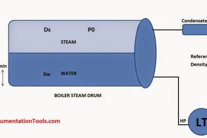
Bi-colour type level gauges shall be used on steam drums. Large chamber gauge glasses and an expansion loop between the top of the gauge and the top gauge valve shall be used. Level gauges on steam/boiler drums shall be in accordance with the latest requirements of the IBR code.
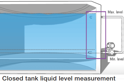
The Level gauge shall provide visible coverage of complete level transmitter/controller range and the alarm/trip level switches. In the case of differential pressure level transmitters where large spans are involved, a gauge located at the top, center, and bottom of the installation with an overlap in visible area shall be acceptable.
Magnetic Coupled Level Gauge
Magnetic coupled level gauges shall be preferred over gauge glasses. Where magnetic level gauges are not suitable for services such as high temperature etc steel armored reflex or transparent type shall be considered.
Wherever gauge glasses are considered, they shall be with body & cover material of forged steel and shall have mechanical & thermal shock resistant type toughened borosilicate glass with suitable gasket. Bolting shall be of SAE 4140 steel.
Transparent type of gauges shall be provided with integral illuminators operating at 240 V 50 Hz supply and suitable for electrical area classification specified.
Illuminator shall be of the plastic solid wedge type designed to give an even diffusion of light over the entire length of the gauge glass. All gauge glasses must have a rating equal to or more than the vessel design pressure and temperature and shall be provided with a suitable metal guard.
Reflex Level Gauge
Reflex type shall be used for clean and colorless liquids like water and hydrocarbon service, except liquids interface level.
For low temperature, low boiling point service, foaming liquids, large chamber type will be used. Transparent type will be used for light fluids, acids, caustic, dirty or viscous liquids, colored liquids, and liquids interface level.
Transparent Level Gauge
Transparent type with Mica or Kel-F shields shall be used for treated water, boiler, and condensate services and for corrosive liquids which will attack the glass.
Tubular gauge glasses shall, in general, not be used. They may be used for non-hazardous services at ambient temperature and low pressures.
General Specifications
All gauges shall have top and bottom chamber connections unless otherwise specified. Vent and Drain valves shall be fitted, as applicable. Vent and drain valve shall be provided with nipple and end caps.
Drain and vent shall be of welded construction. Level gauges with side-side connections shall be avoided. Each gauge shall be provided with ball check valves & pipe union.
Large chamber gauges with frost shields shall be provided for cold services below 0ºC. Frost shield shall be transparent plastic-type covering the full width of vision slot and suitably sealed to the glass.
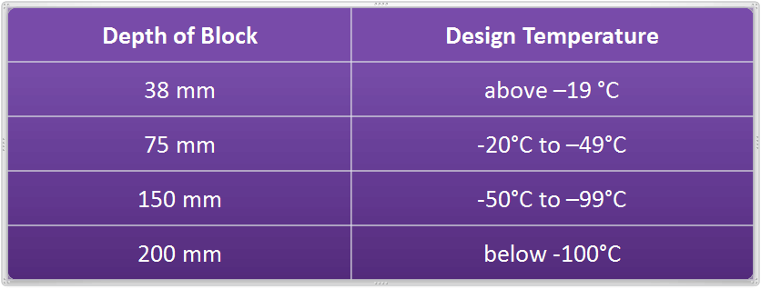
The heating jackets shall be provided for viscous liquids.
In general, the visible length of the level gauges shall be selected from the following:
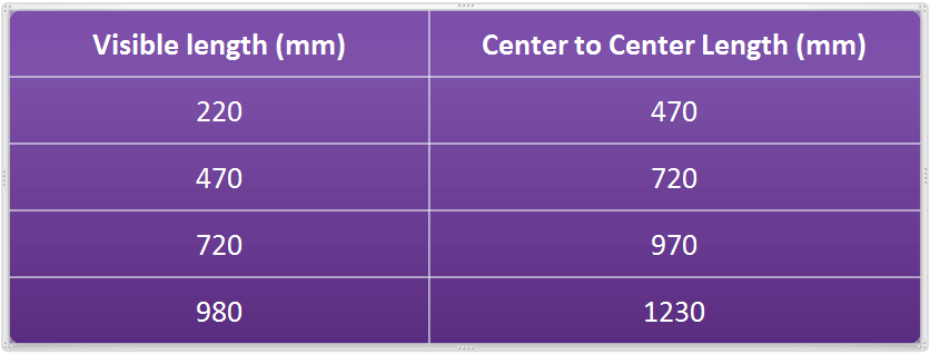
The maximum visibility length shall not exceed 1500 mm for a single gauge. Multiple gauges with overlapping range shall be used for such cases. For a given section, the visible length shall not be less than 90% of the total length of the section.
Gauge glass cocks shall be forged offset type with integral ball check and back seating stem. Primary isolation valves are normally required in addition to the gauge glass cocks, except on vented tanks containing harmless liquids. Where the process fluid tends to foul the cocks internals and create plugging or where the leakage is a problem, the gauge valve may be eliminated.
On low-temperature service with liquids having very high vapor pressure at ambient temperature safety valve shall be provided at the vent connection of the gauge glass.
Gauge cocks may be deleted or ball checks omitted when the fluid is not toxic/corrosive/inflammable at high pressure and when there is a possibility of sluggish action. If ball checks are used, it shall be checked that the process pressure is high enough to drive the ball in case of breakage.
Interest to add any further points? Share with us through below comments section.
Author: Kalpit Patel
Read Next:
- Types of Level Gauges
- Selection of Level Gauges
- Tank Gauging Methods
- Dip Level Measurement
- Servo Tank Gauging


Dear Admin,
Can you please add standard reference for every article that you provided?
Example:
If we talk about P&ID, then ISA 5.1 is the standard, etc.
It will very usefull for us to learn about the knowledge that you provide with existing standards